
Problem
In a previous tip on Install SQL Server 2008 on a Windows Server 2008 Cluster Part 1, we have seen how to install and configure a SQL Server 2008 on a Windows Server 2008 Failover Cluster. We now have a new requirement to deploy a SQL Server 2012 instance on a multi-subnet cluster that spans different geographical locations. How do I install and configure a SQL Server 2012 on a multi-subnet cluster?
Solution
To continue this series on Installing SQL Server 2012 on a Multi-Subnet Cluster, we will look at building our Windows Server 2008 R2 cluster in preparation for SQL Server 2012. In Part 1, we have configured the storage in both of the servers that we will be using as part of our cluster. Now, that doesn’t mean we’re done with the storage part. Remember that this is a key component in setting up your multi-subnet cluster so we will make modifications as necessary prior to installing SQL Server 2012. Your storage engineers and vendors will be able to assist you with making the necessary configuration to make the storage suitable for a multi-subnet cluster.
This tip will walk you through the creation of the Windows Server 2008 R2 Multi-Subnet Cluster. It is assumed at this point that you have installed the Failover Clustering feature together with the .NET Framework 3.5.1 using Server Manager. If you haven’t done so, check out this tipfor reference.
Running the Failover Cluster Validation Wizard
When you run the Failover Cluster Validation Wizard, make sure you select all of the tests and don’t skip any items, specifically the storage tests. This is highly recommended because the Failover Cluster Validation Wizard will tell you whether or not you still need to make modifications on your storage subsystem.

In my case, I had to further configure the MPIO settings on my iSCSI storage before I got a successful test result.

Creating the Windows Server 2008 R2 Multi-Subnet Cluster
Once you get a successful test result on the Failover Cluster Wizard, you are now ready to create your Windows Server 2008 R2 Multi-Subnet Cluster. Make sure that you already have the virtual server name and virtual IP addresses that you will assign for the Windows Failover Cluster. Now, you might be wondering why I said IP addresses (plural, not singular). That wasn’t a typographical error. Since you are dealing with multiple subnets for this cluster, you need to have a corresponding virtual IP address per subnet for the virtual server name. The number of virtual IP address will depend on the number of subnets you will be using for your failover cluster. In this example, since I am only dealing with two subnets, I only need two virtual IP addresses for every virtual server name – including the SQL Server cluster resource which we will see later on when we install SQL Server 2012 on this cluster.
To run the Create a Cluster Wizard:
- Open the Failover Cluster Management console.
- Under the Management section, click the Create a Cluster link. This will run the Create Cluster Wizard.

- In the Select Servers dialog box, enter the hostnames of the nodes that you want to add as members of your cluster and click Next.

- In the Access Point for Administering the Clusterdialog box, enter the virtual hostname and IP addresses that you will use to administer the cluster. As I’ve previously mentioned, notice that you now have two sections for the virtual IP address – one for each subnet. The wizard is smart enough to detect that you are trying to create a multi-subnet cluster. This is possible because of the implementation of the OR logic in the cluster resource dependency (more on this in a later section). For this example, I will use the following information:
Virtual Server Name Networks IP Address WINMULTISUBCLUS 172.16.0.0/24 172.16.0.112 192.168.0.0/24 192.168.0.112 Click Next.
- In the Confirmation dialog box, click Next. This will configure Failover Clustering on both nodes of the cluster, add DNS and Active Directory entries for the cluster virtual server name.
Click Next.

- In the Summarydialog box, verify that the report returns successful results.
Click Next.


That was it. You now have a working Windows Server 2008 R2 multi-subnet cluster. One thing that you’ll notice in the report is that it automatically configured the quorum to use node and disk majority. This is the default configuration for a cluster with an even number of nodes and accessible shared storage. While you can use node and disk majority quorum configuration for a multi-subnet cluster, it doesn’t make sense to replicate the storage between subnets just for this purpose. A recommended quorum configuration for this setup is to use the node and file share majority. A detailed explanation of quorum configuration can be found in this Microsoft TechNet article. We will configure the cluster quorum settings in a while but before we do, let’s take a look at what other cluster and network configuration we need to set prior to installing SQL Server 2012.
Understanding the OR Logic in Dependencies
As I mentioned in the previous tip, multi-subnet clustering has been available ever since Windows Server 2008. This is because it implements the OR logic in dependencies for cluster resources. In the past, cluster resource dependencies implement an AND logic. This means that if a cluster resource X is dependent on resources A and B, both of the cluster resources need to be online in order for cluster resource X to be online. If either A or B is offline, cluster resource X will not go online. With the implementation of the OR logic dependency, the cluster resource X can now be brought online even when one of the dependency resources is not.
To better understand this concept, let’s look at the Cluster Core Resources section of the Windows Failover Cluster. Expand the virtual server name to see the two virtual IP addresses that we have assigned.

Notice how the virtual server name WINMULTISUBCLUS is online even when the virtual IP address 192.168.0.112is offline. If you check the properties of the virtual server name, you will see that the cluster has automatically defined this OR logic dependency for us when we were creating the cluster.

This OR logic dependency on the virtual IP address is what makes it possible for the cluster to go online on any of the subnets when failover happens. We will see this again in action when we install SQL Server 2012 Failover Cluster.
Tuning Cluster Heartbeat Settings
In a multi-subnet cluster, we need to test network latency to make sure that the nodes do communicate with each other. The communication between cluster nodes, more commonly known as the “heartbeat“, needs to be properly configured for the cluster to work efficiently. Inefficient communication between cluster nodes may trigger a false failover, thus, it is necessary to properly tune the heartbeat settings.
There are two major settings that affect heartbeat. First, the frequency at which the nodes send signals to the other nodes in the cluster (subnet delays) and second, the number of heartbeats that a node can miss before the cluster initiates a failover (subnet threshold). In a single-subnet cluster, we barely made modifications to these settings because the delay (about 250 to 2000 milliseconds) and threshold values are tolerable enough for the cluster to handle without initiating a false failover. However, in a multi-subnet cluster, when the cluster nodes are too far away from each other, the communication may take longer and could possibly miss heartbeats. The table below outlines the default values for cluster subnet delays and thresholds.
| Heartbeat Parameter | Default value |
| SameSubnetDelay | 1000 (in milliseconds) |
| SameSubnetThreshold | 5 heartbeats |
| CrossSubnetDelay | 1000 (in milliseconds) |
| CrossSubnetThreshold | 5 heartbeats |
We can view the cluster parameters to see their default values. Note, that while we can still use the cluster.exe command, I will use the FailoverClusters module in Windows PowerShell.
PS C:\> Get-Cluster | Format-List *

This simply means that, by default, a heartbeat is sent every 1 second to all of the nodes in the cluster – both single subnet and multi-subnet. If 5 heartbeats are missed, the node is considered down and failover is initiated. We can change these values based on the performance of our network infrastructure. A simple PING test can be done between nodes of a multi-subnet cluster to get an idea of response times between nodes. For this example, let’s say we will configure our cross subnet delay value to 3 seconds instead of 1 and a threshold value of 7 instead of 5.
PS C:\> $clust = Get-Cluster; $clust.CrossSubnetDelay = 3000; $clust.CrossSubnetThreshold = 7

This now changes the behavior of the cluster heartbeat to be more tolerable across multiple subnets.
Configuring the Cluster Quorum Settings
As previously mentioned, the cluster quorum settings that the wizard selected for us used the Node and Disk Majority option. Since it doesn’t make sense for us to replicate the cluster storage just for this purpose, we will configure the cluster quorum settings to use Node and File Share Majority. This also gives us the benefit of allocating the cluster storage for other cluster resources. This is Microsoft’s recommendation for multi-subnet clusters with even number of nodes. Before we change the configuration, we need to create a file share and grant the Windows Failover Cluster virtual server name Read/Writepermissions to it.
The placement of the file share witness is a bit of a debate as well. While the ideal case is to place it in a different geographic location than the cluster nodes, sometimes cost dictates otherwise. Microsoft Clustering MVP David Bermingham wroteabout the different options on where to place the file share witness. I’m all for this recommendation, but if cost is preventing us from doing so, you can place it on the production site provided that you constantly monitor the file share witness and host it in a highly available file server.
To configure the quorum in a failover cluster:
- Open the Failover Cluster Management console
- Select the name of the cluster you have just created. Right-click on the cluster, select More Actions, and click Configure Cluster Quorum Settings… This will open up the Configure Cluster Quorum Wizard

- In the Select Quorum Configuration dialog box, select the Node and File Share Majority (for clusters with special configuration) option. Click Next.

- In the Configure File Share Witness dialog box, provide the file share location that you want your cluster to use as the quorum/witness. In my example, AD2 is a domain controller in another location that is different from my cluster nodes. Click Next

- In the Confirmation dialog box, verify that the file share configuration for the quorum/witness is correct. Click Next.

- In the Summary dialog box, verify that the entire configuration is successful.


You can verify that the cluster quorum setting is now configured to use the file share witness by looking at the Cluster Core Resourcessection.

In this tip, we have created a Windows Server 2008 multi-subnet cluster and configured the heartbeat and quorum settings. Make sure you perform validation testing to make sure that the cluster is working as expected. In the next tip, we will proceed to install SQL Server 2012 in our fully working multi-subnet cluster.
Next Steps
- Review the previous tips on Install SQL Server 2008 on a Windows Server 2008 Cluster Part 1, Part 2, Part 3 and Part 4.
- Download and install an Evaluation copy of Windows Server 2008 R2 for this tip and SQL Server 2012in preparation for the next one.
- Start working on building your test environment in preparation for setting up a SQL Server 2012 multi-subnet cluster on Windows Server 2008 R2. This is a great opportunity to learn more about networking concepts and fundamentals as a SQL Server DBA.
-
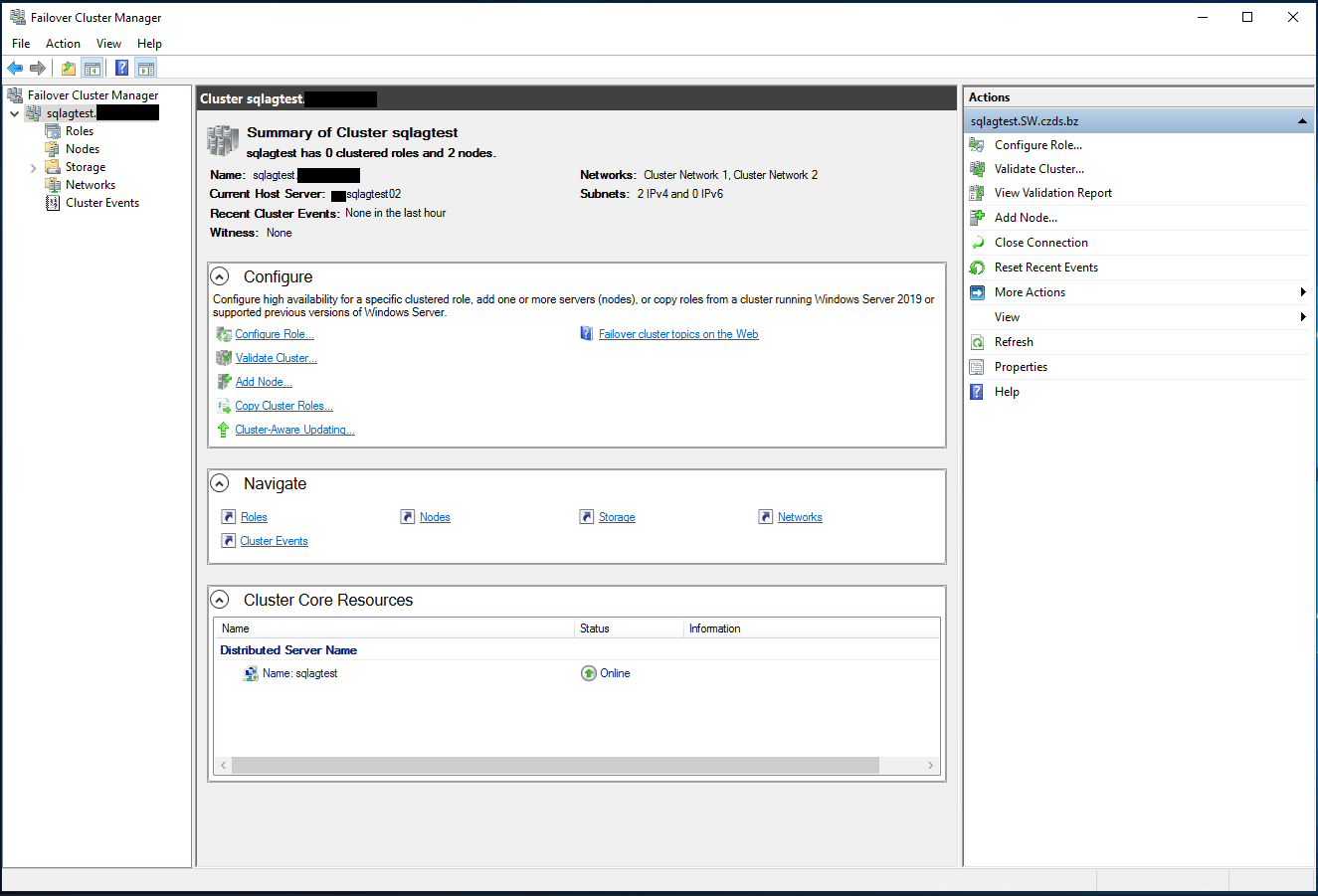
This section describes the creation of a Windows Server 2022 multi-subnet failover cluster from the Failover Cluster Management console.
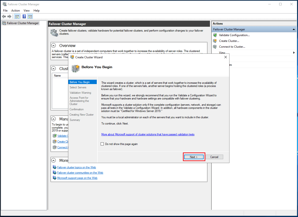
You can launch the tool from the Server Manager dashboard, under Tools and select Failover Cluster Manager. Alternatively, the Create Cluster Wizard automatically runs after the Failover Cluster Validation Wizard runs for the first time.
- Under the Management section, click the Create a Cluster link as shown in the following figure. This runs the Create Cluster Wizard.

Figure 18. Create a cluster
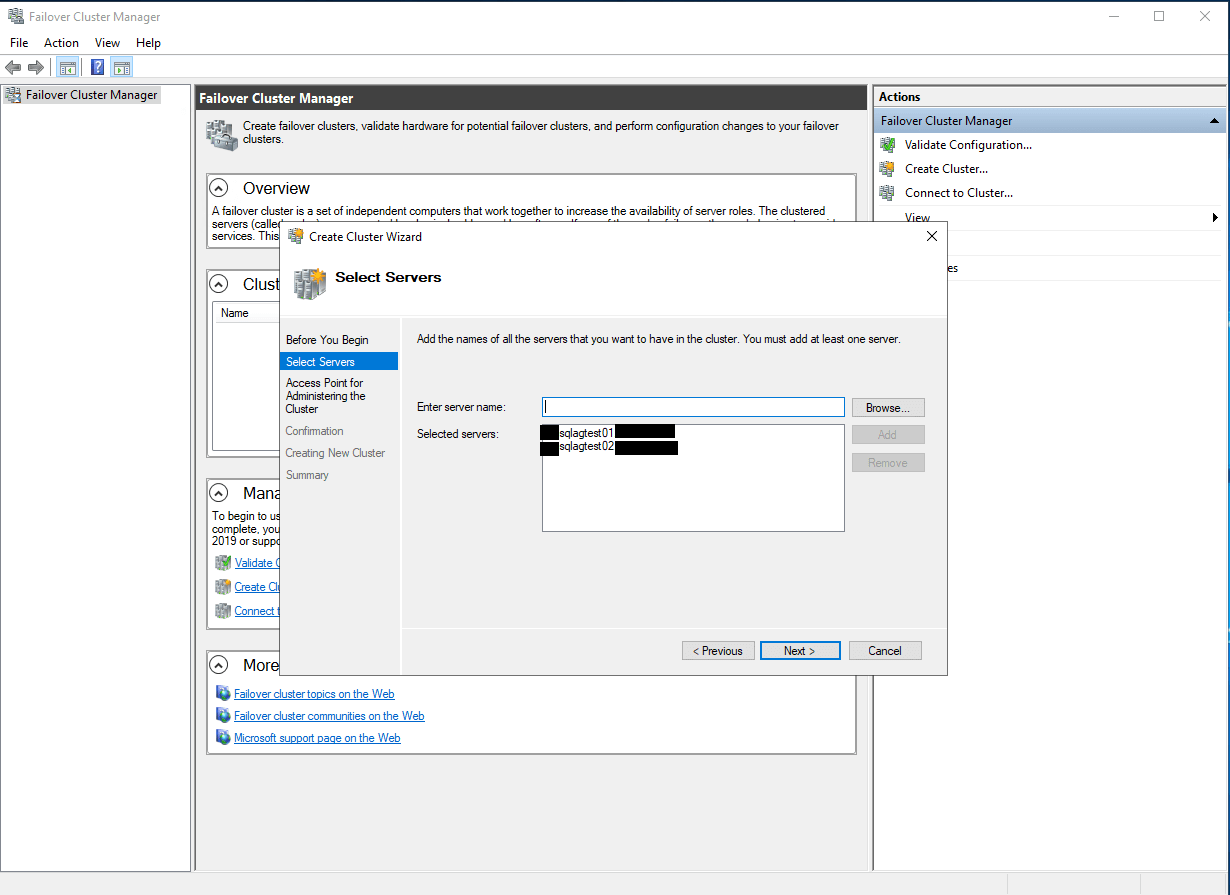
- In the Select Servers dialog box, and enter the hostnames of the nodes that you want to add as members of your cluster as shown in the following figure. Click Next.
Figure 19. Selecting servers or a cluster
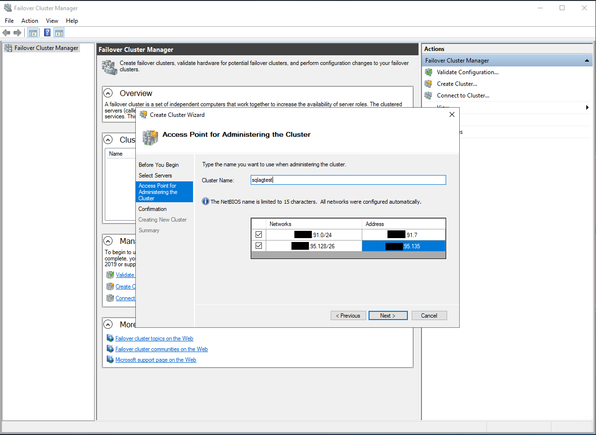
- In the Access Point for Administering the Cluster dialog box, enter the Windows Server Failover Cluster virtual hostname and IP addresses that you use to administer the cluster. Notice that you now have multiple sections for the virtual IP address — one for each subnet as shown in the following figure. Click Next.
Note: only assign the virtual IP addresses configured in DNS for the production network. Since the DNS addresses contain all the subnets, the cluster node will be reachable, regardless in which AZ it happens to be available.
Figure 20. Administering the cluster
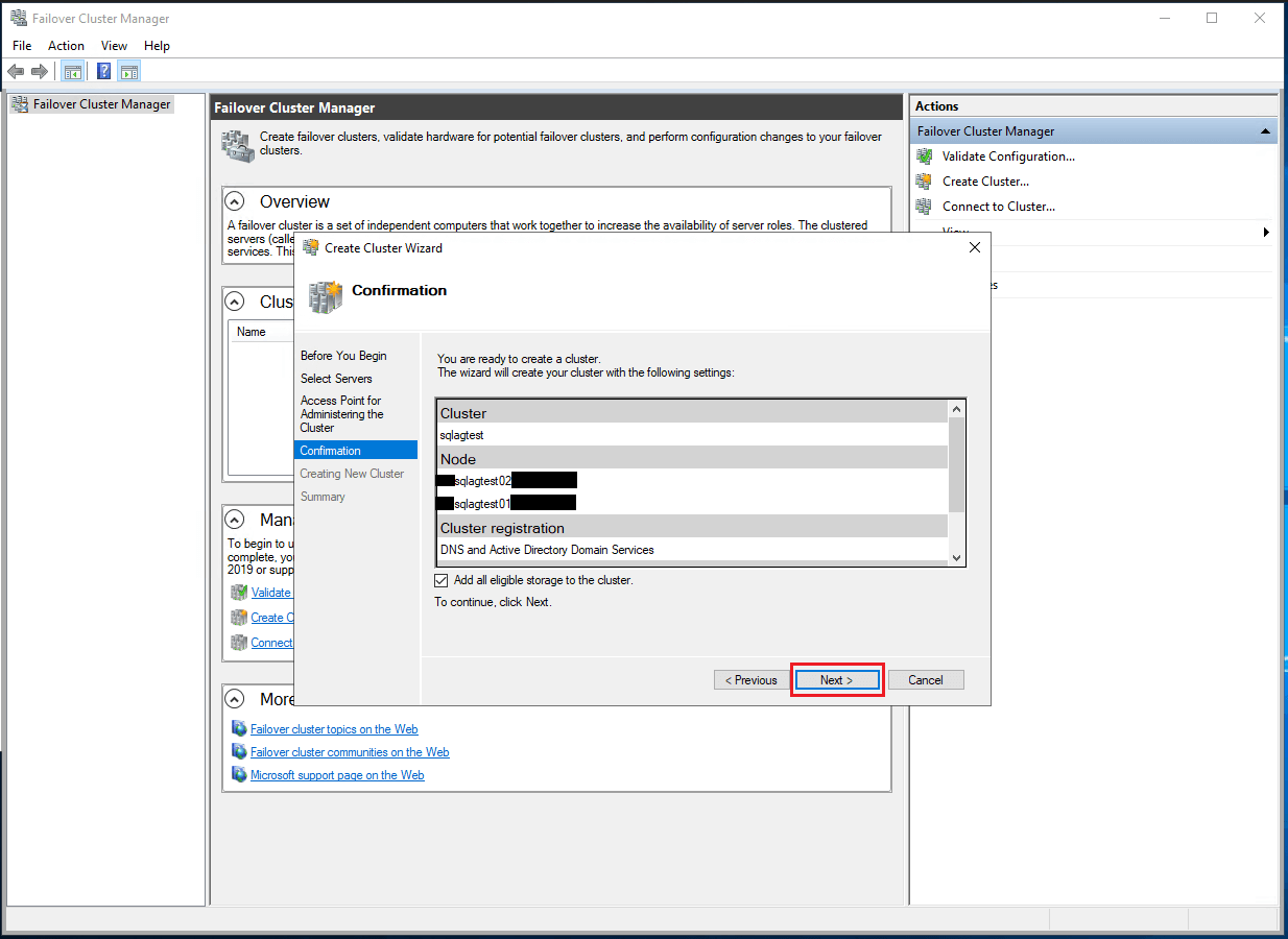
- In the Confirmation dialog box, click Next as shown in the following figure.
This configures the Failover Clustering on all nodes of the cluster. Add the configured cluster storage, Active Directory, and DNS entries for the cluster virtual server name.
Figure 21. Confirmation to create a cluster
- In the Summary dialog box, verify that the report returns successful results as shown in the following figure:
Figure 22. Cluster summary


In this article, we will learn how to set up Azure SQL VM AOAG based on Windows Server 2019 Failover Cluster step-by-step, it is a detailed supplement to the Microsoft official articles and it is a beginner’s guide for people who have no experience to do that, please read this article closely with Mircosoft’s guide: https://docs.microsoft.com/en-us/azure/azure-sql/virtual-machines/windows/availability-group-manually-configure-prerequisites-tutorial-multi-subnet?view=azuresql
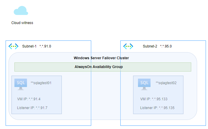
Architecture
There are two subnets created in Azure, and each node in the cluster with two IP addresses, one for VM itself and another for the AG listener:
Prerequisites
When you finished the step «Join the servers to the domain» in Microsoft articles, please check the following configuration on both nodes:
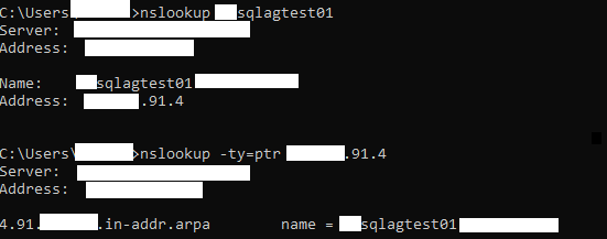
- DNS resolution
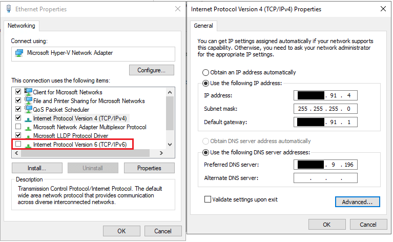
2. Set static IP configuration of Azure SQL VM and disabled IPv6 on NIC
Notes: Prerequisites are very important! You can’t configure the cluster successfully if you do not do it!
Step up Cluster:
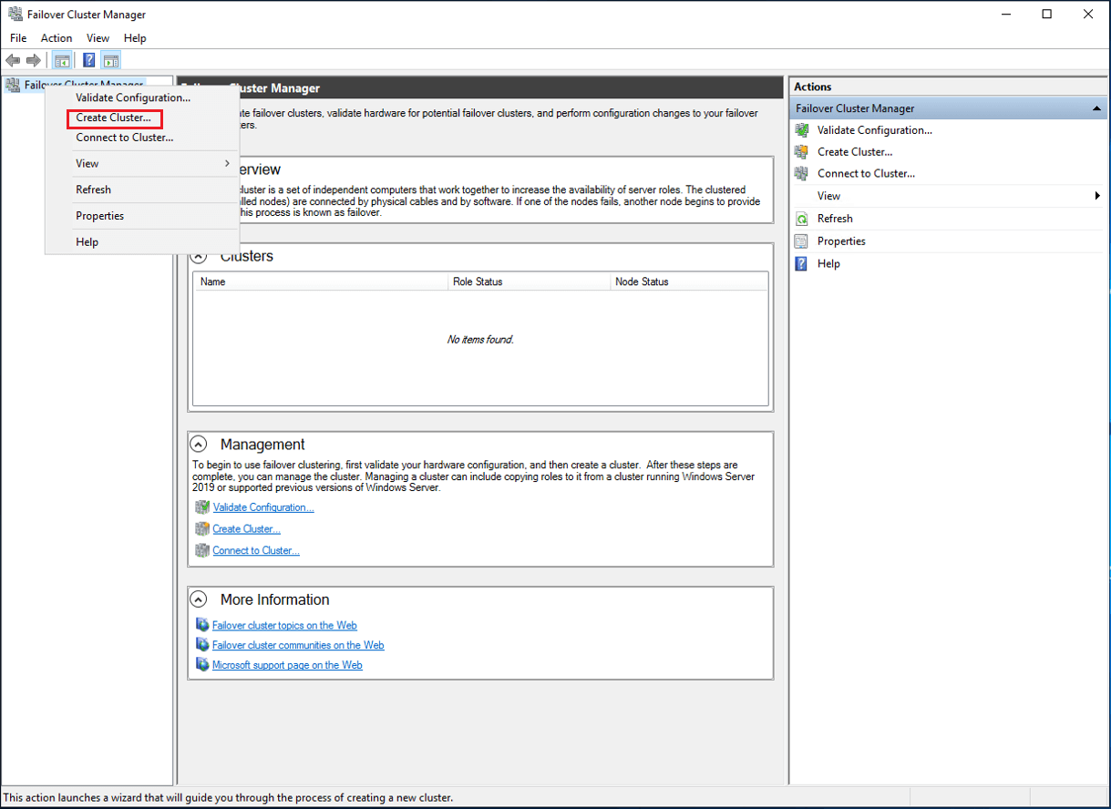
Step 1: Go to Failover Cluster Manager, and click on «Create Cluster»
Step 2: Open the wizard, and click on «Next»
Step 3: Select servers which need to add to the cluster:
Step 4: Input access point.
Notes:
1) Please input the IP addresses of AG listeners! Don’t worry that these IP addresses can not be used for AG listeners because this will not happen, since Windows Server 2019 Failover cluster uses the Distributed Server Name instead of the Cluster Network Name, so the inputted IP addresses are not exclusive to the cluster.
2) If your first time creating the cluster on the server it probably uses Cluster Network Name but not Distributed Server Name, in this case, you can just delete the cluster then you can create it again, the new cluster you create will automatically convert to using Distributed Server Name!
Step 5: Confirm the configuration and click on «Next»
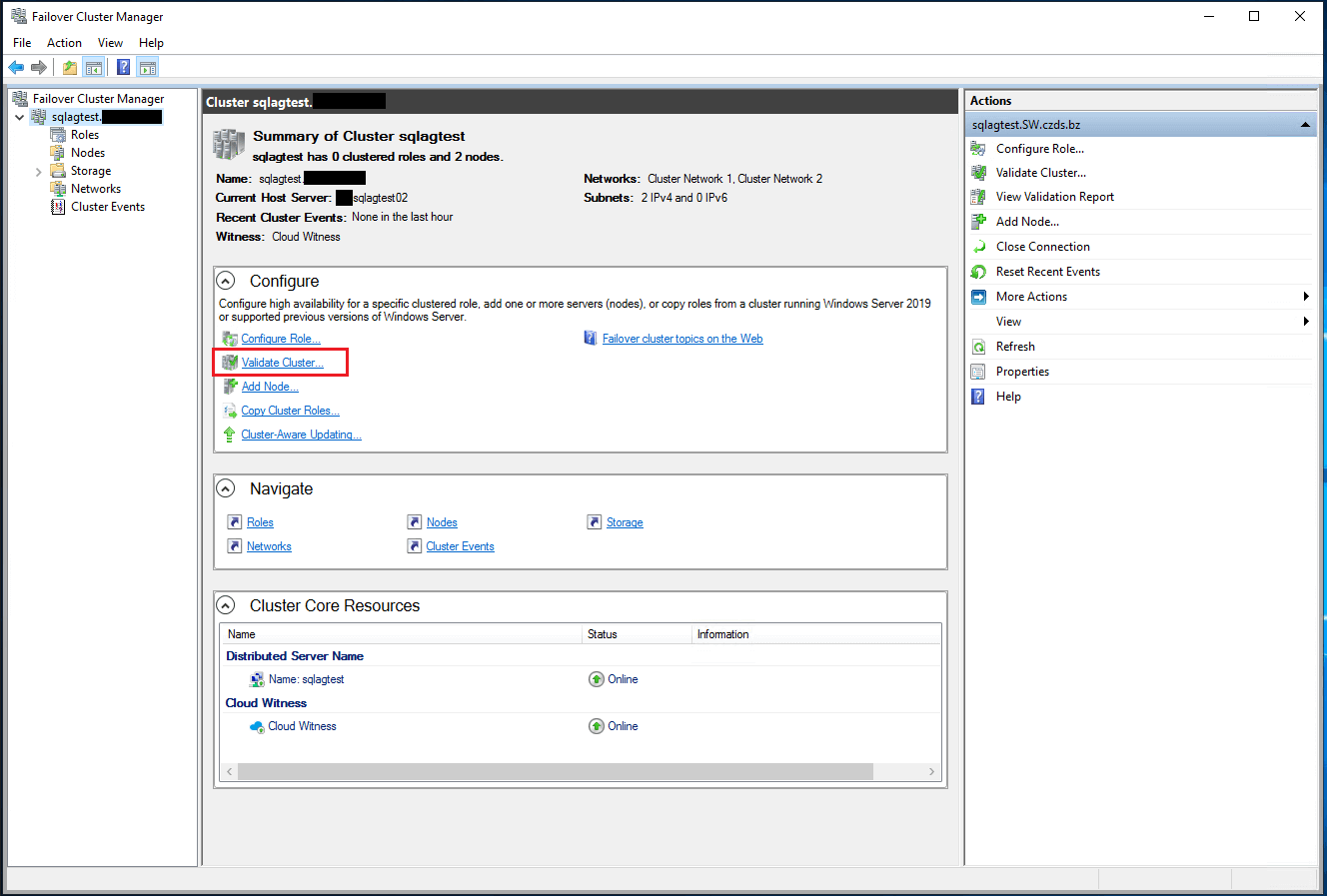
Validation of the cluster DNS resolution
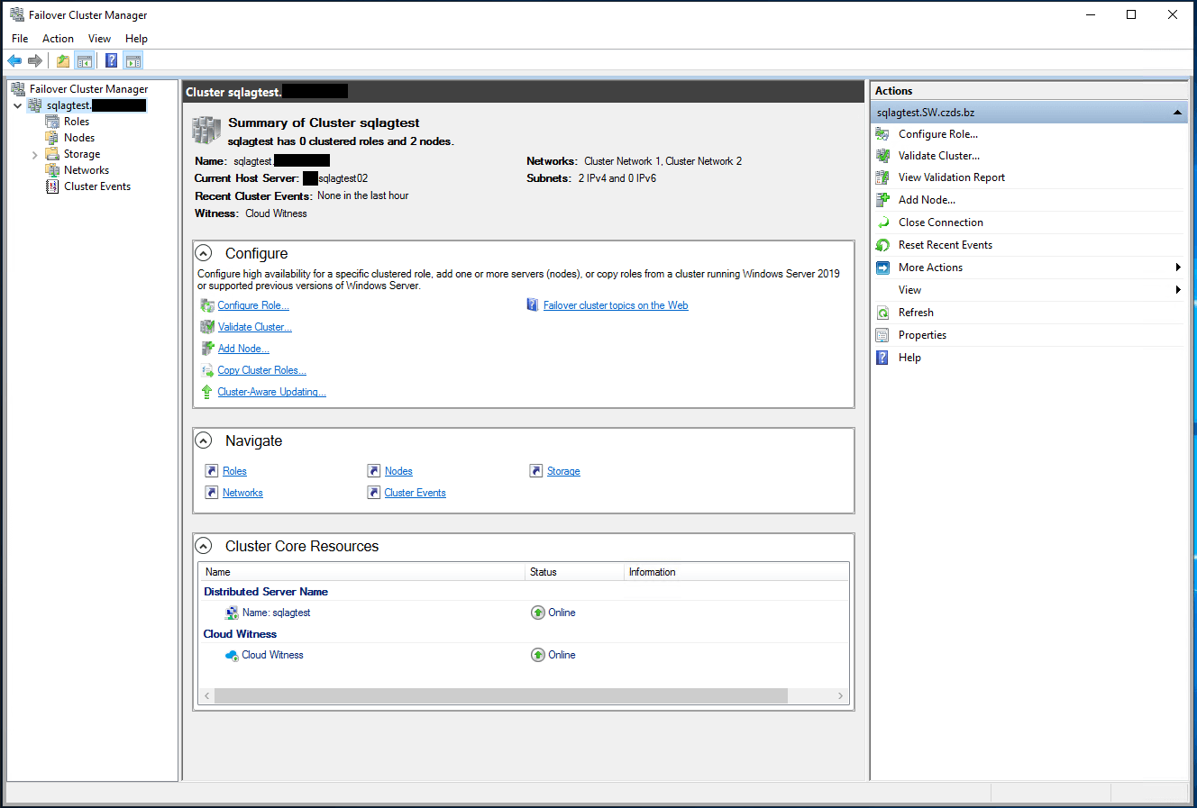
Step 6: Create the Cloud witness
Please refer to Microsoft’s guide: https://docs.microsoft.com/en-us/windows-server/failover-clustering/deploy-cloud-witness
Run this Powershell script on one node in the cluster:
[Net.ServicePointManager]::SecurityProtocol=[Net.SecurityProtocolType]::Tls12
Set-ClusterQuorum -CloudWitness -AccountName "youraccountname" -AccessKey "youraccesskey"
As the result, you will see the WSFC status:
Validation of the cluster failover:
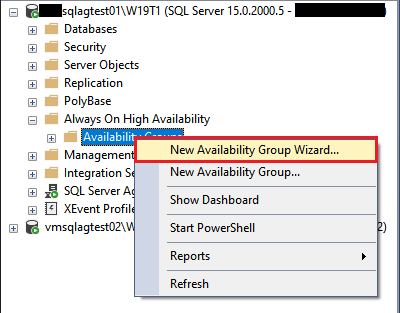
Set up AOAG:
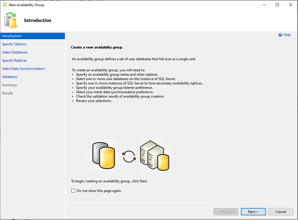
Step 1: Go to the «New Availability Group Wizard»:
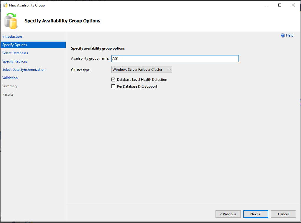
Step 2: Input the Availability group name and choose cluster type:
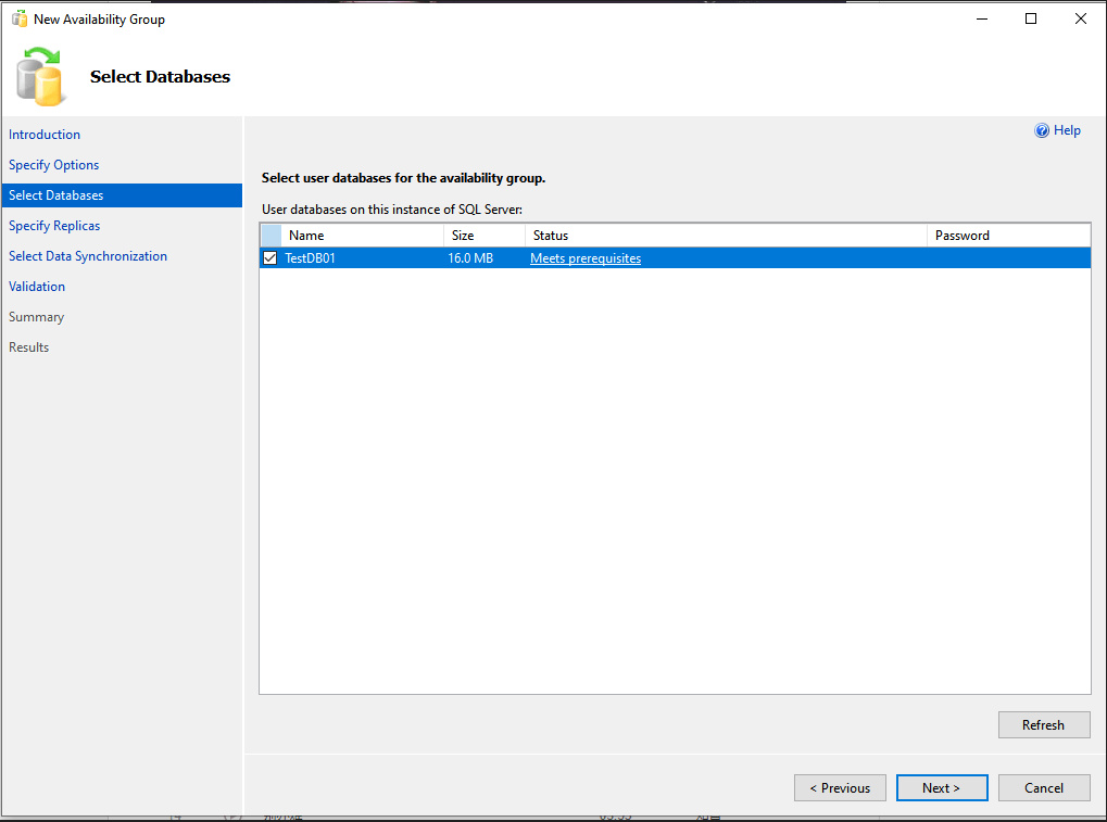
Step 3: Choose the databases which need to add to the availability group:
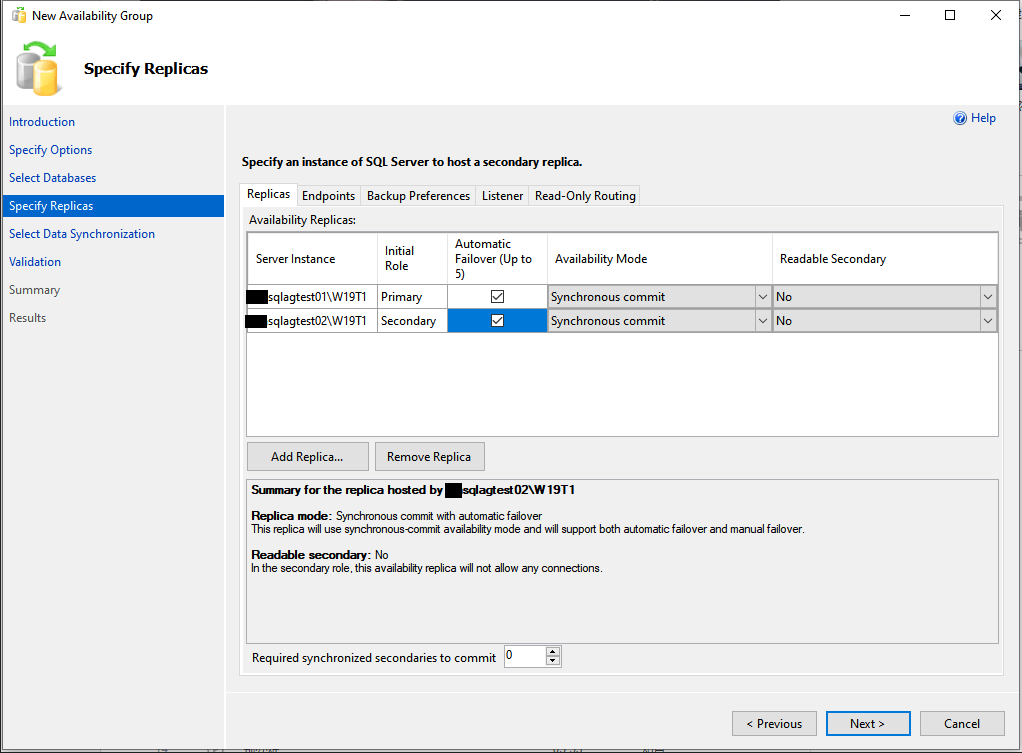
Step 4: add the secondary replica and set the
Step 5: Create the DNS name for the AG listener:
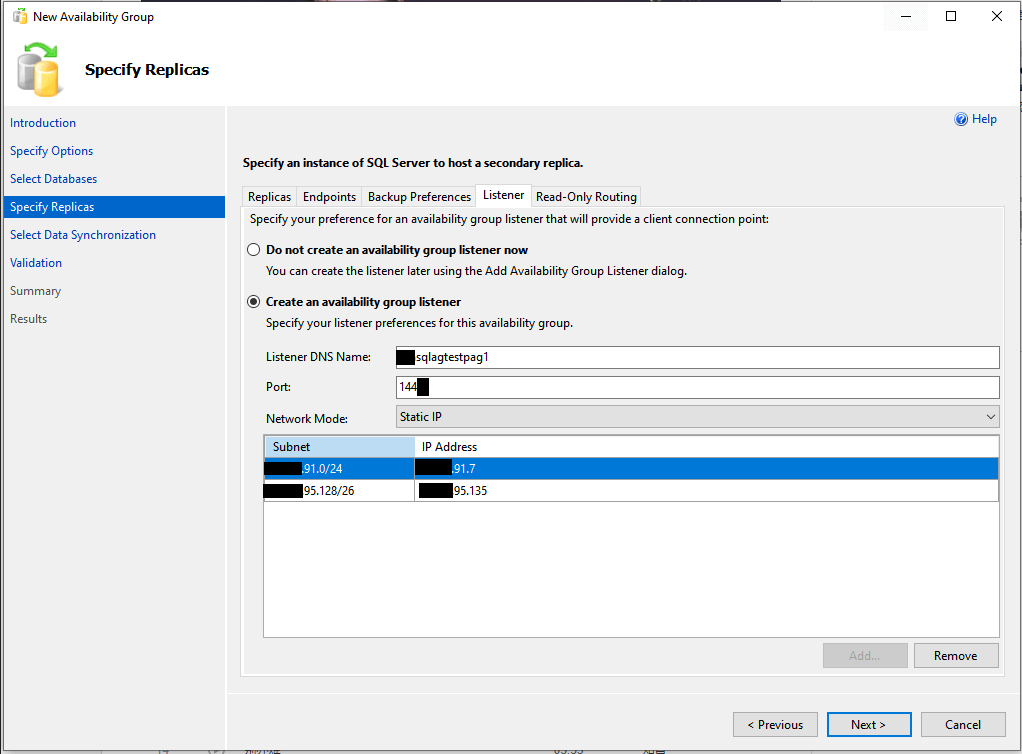
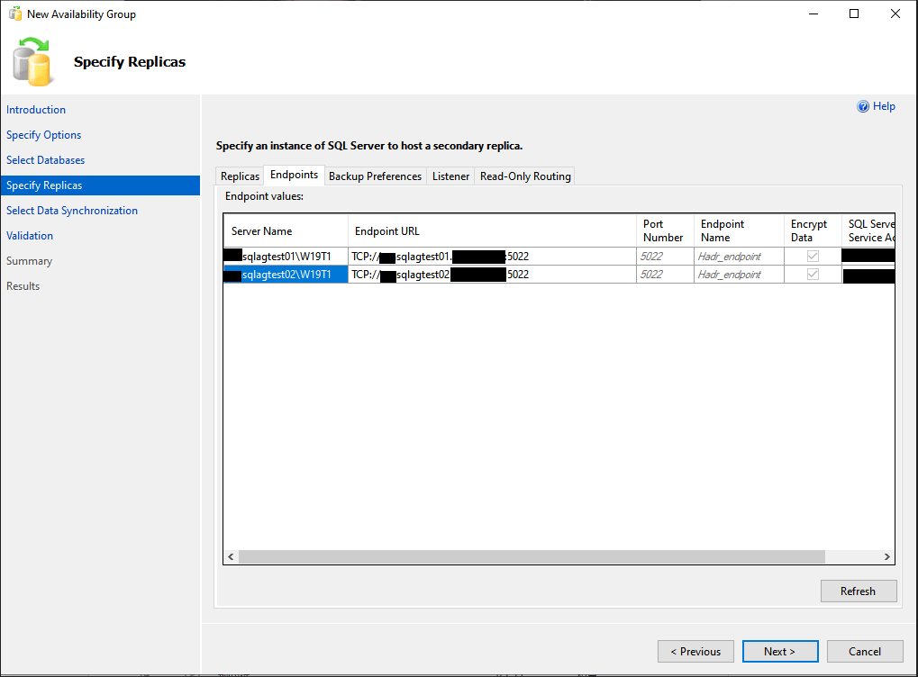
Step 6: Set the endpoint for both replicas:
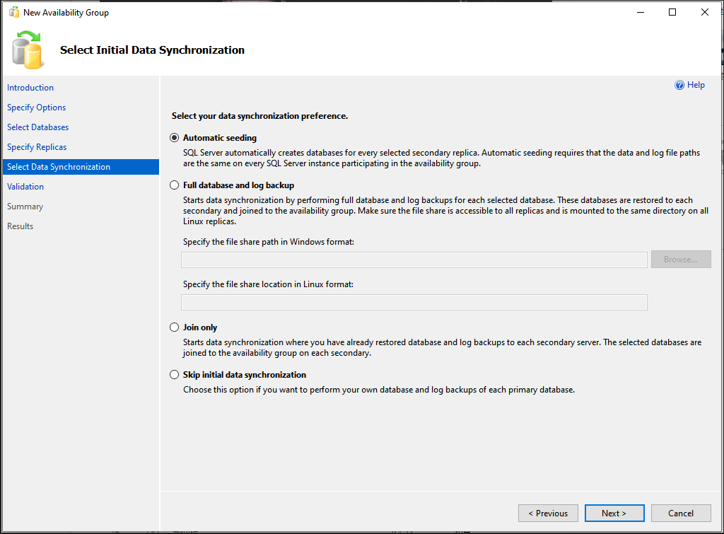
Step 7: Select the data synchronization preference:
Notes: If you choose to use «Automatic seeding», please make sure you have the same data and log file paths on both replicas.
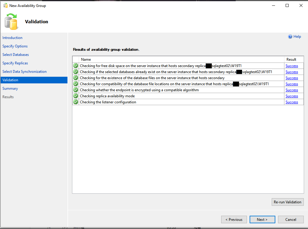
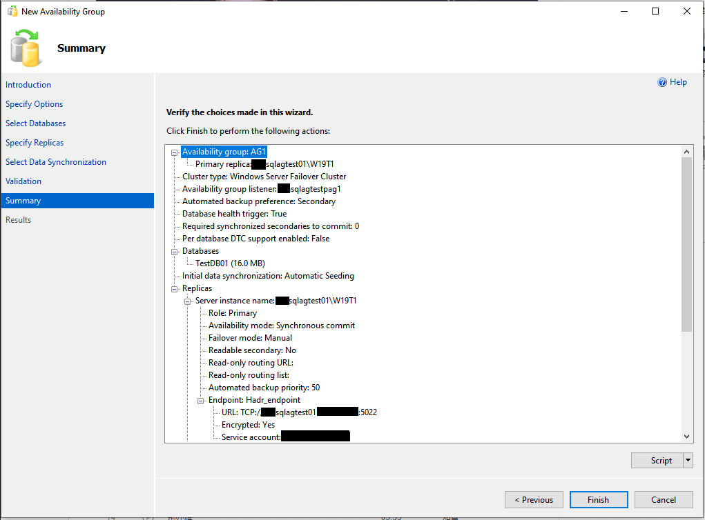
Step 8: Validate the AG configuration:
Step 9: Select «Finish» to execute the configure tasks:
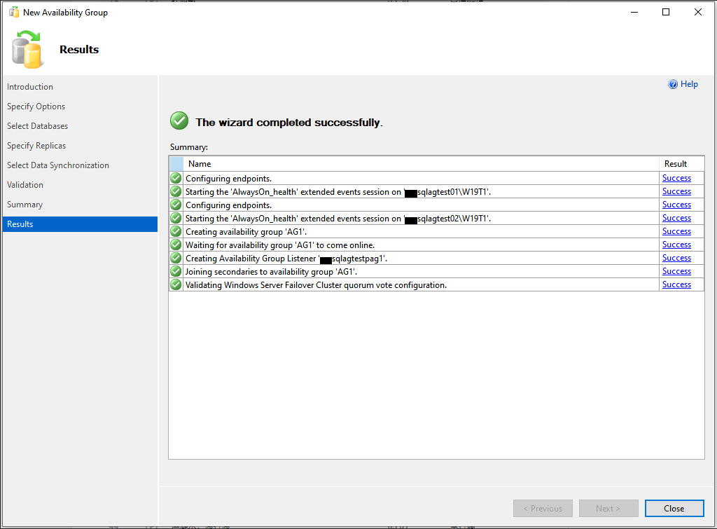
Here you can get the configuration results:
Notes: If you failed with the following error, usually it means the cluster without permission to create the DNS record, please check it with your AD administrator.
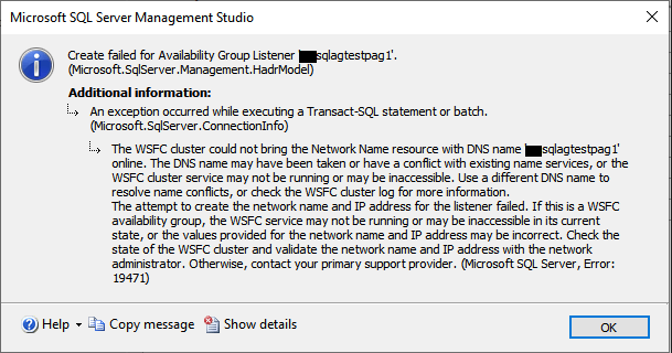
Also you can refer this KB from Microsoft:
https://support.microsoft.com/en-us/topic/kb2829783-troubleshooting-alwayson-availability-group-listener-creation-in-sql-server-2012-42b42543-3c4b-49e3-14fc-5bc76e7eec89
This article is contributed. See the original author and article here.
In the Windows world, a Windows Server Failover Cluster (WSFC) natively supports multiple subnets and handles multiple IP addresses via an OR dependency on the IP address. On Linux, there is no OR dependency, but there is a way to achieve a proper multi-subnet natively with Pacemaker, as shown by the following. You cannot do this by simply using the normal Pacemaker command line to modify a resource. You need to modify the cluster information base (CIB). The CIB is an XML file with the Pacemaker configuration.
That’s the comment from https://docs.microsoft.com/en-us/sql/linux/sql-server-linux-configure-multiple-subnet?view=sql-server-ver15
However, the steps of modifying CIB is not correct. MS will revise the steps soon.
Here is an example to create a SQL Server Linux Availability group in 4 nodes in 3 subnets in RHEL 7.6
If you are already familiar with the AG Group setup process, please just jump to step 16.
1.Register your subscription on for all servers (red1,red2,red3 and red4 in this case)
subscription-manager register
2.List all available subscription, pick the one with High Availabiilty , notedown the pool id
subscription-manager list –available –all
3.Register the subscription for all nodes (red1,red2,red3 and red4 in this case)
sudo subscription-manager attach –pool=xxxxx
4.Enable the repository(red1,red2,red3 and red4 in this case)
sudo subscription-manager repos –enable=rhel-ha-for-rhel-7-server-rpms
5.Install Pacemaker packages on all nodes. (red1,red2,red3 and red4 in this case)
sudo yum install pacemaker pcs fence-agents-all resource-agents
6.Install SQL Server resource agent (red1,red2,red3 and red4 in this case)
sudo yum install mssql-server-ha
7.Set the password for the default user that is created when installing Pacemaker and Corosync packages. All the password should be exactly same (red1,red2,red3 and red4 in this case)
sudo passwd hacluster
8.Update /etc/hosts file in all servers, add IP and node name. All the servers should have the same entries.
192.168.2.103 red1
192.168.2.104 red2
192.168.4.100 red3
192.168.5.101 red4
9.Run following commands to Enable and start pcsd service and Pacemaker in all nodes. (red1,red2 and red3 and red4 in this case)
sudo systemctl enable pcsd
sudo systemctl start pcsd
sudo systemctl enable pacemaker
10.Run following commands to Create Cluster in primary replica node (red1 in this case)
sudo pcs cluster auth red1 red2 red3 red4 -u hacluster -p YouPasswordUsedinStep7
sudo pcs cluster setup –name sqlcluster1 red1 red2 red3 red4
sudo pcs cluster start –all
sudo pcs cluster enable –all
11.Run following command to Enable cluster feature in all nodes(red1,red2 , red3 and red4 in this case)
sudo /opt/mssql/bin/mssql-conf set hadr.hadrenabled 1
sudo systemctl restart mssql-server
Create AG and Listener
1.Run following queries in red1 to create certificate
use master
go
CREATE MASTER KEY ENCRYPTION BY PASSWORD = ‘**<Master_Key_Password>**’;
go
CREATE CERTIFICATE dbm_certificate WITH SUBJECT = ‘dbm’;
go
BACKUP CERTIFICATE dbm_certificate TO FILE = ‘/var/opt/mssql/data/dbm_certificate.cer’
WITH PRIVATE KEY (
FILE = ‘/var/opt/mssql/data/dbm_certificate.pvk’,
ENCRYPTION BY PASSWORD = ‘**<Private_Key_Password>**’
);
2.Run following commands in red1 to copy the certificate to rest of the servers(red2,red3 and red4 in this case)
cd /var/opt/mssql/data
scp dbm_certificate.* root@red2:/var/opt/mssql/data/
scp dbm_certificate.* root@red3:/var/opt/mssql/data/
scp dbm_certificate.* root@red4:/var/opt/mssql/data/
3.Give permission to the mssql user to access the certificate files in rest of the servers(red2,red3 and red4 in this case)
cd /var/opt/mssql/data
chown mssql:mssql dbm_certificate.*
4.Run following T-SQL queries to create the certificate in rest of the nodes by restoring the certificate backup file (red2,red3 and red4 in this case)
use master
go
CREATE MASTER KEY ENCRYPTION BY PASSWORD = ‘**<Master_Key_Password>**’
go
CREATE CERTIFICATE dbm_certificate
FROM FILE = ‘/var/opt/mssql/data/dbm_certificate.cer’
WITH PRIVATE KEY (
FILE = ‘/var/opt/mssql/data/dbm_certificate.pvk’,
DECRYPTION BY PASSWORD = ‘**<Private_Key_Password>**’
)
5.Create endpoint in all servers (red1,red2,red3 and red4)
CREATE ENDPOINT [Hadr_endpoint]
AS TCP (LISTENER_PORT = 5022)
FOR DATABASE_MIRRORING (
ROLE = ALL,
AUTHENTICATION = CERTIFICATE dbm_certificate,
ENCRYPTION = REQUIRED ALGORITHM AES
);
ALTER ENDPOINT [Hadr_endpoint] STATE = STARTED;
6.Run following query in primary replica (red1) to create Availability group(Please note, it works for SQL 2019. If you are using SQL 2017, you need to change AVAILABILITY_MODE of one the replica to ASYNCHRONOUS_COMMIT)
CREATE AVAILABILITY GROUP [ag1]
WITH (DB_FAILOVER = ON, CLUSTER_TYPE = EXTERNAL)
FOR REPLICA ON
N’red1′
WITH (
ENDPOINT_URL = N’tcp://red1:5022′,
AVAILABILITY_MODE = SYNCHRONOUS_COMMIT,
FAILOVER_MODE = EXTERNAL,
SEEDING_MODE = AUTOMATIC) ,
N’red2′
WITH (
ENDPOINT_URL = N’tcp://red2:5022′,
AVAILABILITY_MODE = SYNCHRONOUS_COMMIT,
FAILOVER_MODE = EXTERNAL,
SEEDING_MODE = AUTOMATIC),
N’red3′
WITH (
ENDPOINT_URL = N’tcp://red3:5022′,
AVAILABILITY_MODE = SYNCHRONOUS_COMMIT,
FAILOVER_MODE = EXTERNAL,
SEEDING_MODE = AUTOMATIC),
N’red4′
WITH (
ENDPOINT_URL = N’tcp://red4:5022′,
AVAILABILITY_MODE = SYNCHRONOUS_COMMIT,
FAILOVER_MODE = EXTERNAL,
SEEDING_MODE = AUTOMATIC)
ALTER AVAILABILITY GROUP [ag1] GRANT CREATE ANY DATABASE;–grant create any database permission
- Join the AG group, run the following T-SQL queries in all the secondary servers (red2,red3 and red4 in this case)
ALTER AVAILABILITY GROUP [ag1] JOIN WITH (CLUSTER_TYPE = EXTERNAL);
ALTER AVAILABILITY GROUP [ag1] GRANT CREATE ANY DATABASE
8.Run following T-SQL Queries to create database and add it to AG group in primary replica (red1 in this case).
CREATE DATABASE [db1];
ALTER DATABASE [db1] SET RECOVERY FULL;
BACKUP DATABASE [db1] TO DISK = N’/var/opt/mssql/data/db1.bak’;
BACKUP log [db1] TO DISK = N’/var/opt/mssql/data/db1.trn’;
GO
ALTER AVAILABILITY GROUP [ag1] ADD DATABASE [db1];
9.Create SQL login pacemaker in all servers (red1,red2,red3 and red4 in this case).
CREATE LOGIN [pacemakerLogin] with PASSWORD= N’ComplexP@$$w0rd!’
GO
ALTER SERVER ROLE [sysadmin] ADD MEMBER [pacemakerLogin]
10.Run following bash command in red1
sudo pcs property set stonith-enabled=false
- In all SQL Server Linux servers , run following bash commands to save the credentials for the SQL Server login.(red1,red2,red3 and red4) (The password is as same as the one used in step 9)
echo ‘pacemakerLogin’ >> ~/pacemaker-passwd
echo ‘ComplexP@$$w0rd!’ >> ~/pacemaker-passwd
sudo mv ~/pacemaker-passwd /var/opt/mssql/secrets/passwd
sudo chown root:root /var/opt/mssql/secrets/passwd
sudo chmod 400 /var/opt/mssql/secrets/passwd # Only readable by root
12.Create availability group resource at cluster level, run following command on any one of the nodes (just in one server and run just one time).
sudo pcs resource create ag_cluster1 ocf:mssql:ag ag_name=ag1 meta failure-timeout=60s master notify=true
##check the status

13.Run following bash command in primary replica red1 to create one virtual IP resources. The resource name is ‘vip1’, and IP address is 192.168.2.111
sudo pcs resource create vip1 ocf:heartbeat:IPaddr2 ip=192.168.2.111
##check the status

- Create Availability group listener for Availability group ag1. Run following T-SQL query in primary replica (red1 in this case).
ALTER AVAILABILITY GROUP [ag1]
ADD LISTENER ‘aglistener’ (WITH IP
(
(‘192.168.2.111′,’255.255.255.0’),
(‘192.168.4.111′,’255.255.255.0’),
(‘192.168.5.111′,’255.255.255.0’)
),PORT = 1433);
- Run following bash commands to create constraints:
sudo pcs constraint colocation add vip1 ag_cluster1-master INFINITY with-rsc-role=Master
sudo pcs constraint order promote ag_cluster1-master then start vip1

16.Run following bash command to export the CIB.(you can run the command in any node)
sudo pcs cluster cib <filename>

17.You will find following similar entries
<primitive class=”ocf” id=”vip1″ provider=”heartbeat” type=”IPaddr2″>
<instance_attributes id=”vip1-instance_attributes”>
<nvpair id=”vip1-instance_attributes-ip” name=”ip” value=”192.168.2.111″/>
</instance_attributes>
<operations>
<op id=”vip1-monitor-interval-10s” interval=”10s” name=”monitor” timeout=”20s”/>
<op id=”vip1-start-interval-0s” interval=”0s” name=”start” timeout=”20s”/>
<op id=”vip1-stop-interval-0s” interval=”0s” name=”stop” timeout=”20s”/>
</operations>
</primitive>
18.Here is the modified version
<primitive class=”ocf” id=”vip1″ provider=”heartbeat” type=”IPaddr2″>
<instance_attributes id=”vip1-instance_attributes”>
<rule id=”Subnet1-IP” score=”INFINITY” boolean-op=”or”>
<expression id=”Subnet1-Node1″ attribute=”#uname” operation=”eq” value=”red1″/>
<expression id=”Subnet1-Node2″ attribute=”#uname” operation=”eq” value=”red2″/>
</rule>
<nvpair id=”vip1-instance_attributes-ip” name=”ip” value=”192.168.2.111″/>
</instance_attributes>
<instance_attributes id=”vip1-instance_attributes2″>
<rule id=”Subnet2-IP” score=”INFINITY”>
<expression id=”Subnet2-Node1″ attribute=”#uname” operation=”eq” value=”red3″/>
</rule>
<nvpair id=”vip1-instance_attributes-ip2″ name=”ip” value=”192.168.4.111″/>
</instance_attributes>
<instance_attributes id=”vip1-instance_attributes3″>
<rule id=”Subnet3-IP” score=”INFINITY”>
<expression id=”Subnet3-Node1″ attribute=”#uname” operation=”eq” value=”red4″/>
</rule>
<nvpair id=”vip1-instance_attributes-ip3″ name=”ip” value=”192.168.5.111″/>
</instance_attributes>
<operations>
<op id=”vip1-monitor-interval-10s” interval=”10s” name=”monitor” timeout=”20s”/>
<op id=”vip1-start-interval-0s” interval=”0s” name=”start” timeout=”20s”/>
<op id=”vip1-stop-interval-0s” interval=”0s” name=”stop” timeout=”20s”/>
</operations>
</primitive>
- Run following command to import the modified CIB and reconfigure Pacemaker.
sudo pcs cluster cib-push <filename>
Here are the takeaway points:
1).All nodes in same subnet should be in the same <Instance_attributes>

2).If there are more than one servers in the subnet, the keyword ‘boolean-op=”or”’ is a must

3).The IP address of Alwayson Listener is addressed in <nvpair> .

4).The value of id property does not matter, you can specify any value as long as the value is unique.

Optional, you can create three entries for the three IP addresses in the DNS server.

Here is an screenshot of using SQLCMD to connect the AGListener

Brought to you by Dr. Ware, Microsoft Office 365 Silver Partner, Charleston SC.
INTRODUCTION
Disclaimer: Mainstream support for the products mentioned in this guide is expired. Please consider using supported versions of the products.
A SQL Server 2014 multi-subnet failover clustered instance is a configuration where each node of the cluster is connected to a different network subnet or subnets. These network subnets can be in the same location or in a remote site commonly used for disaster recovery. This configuration provides the benefit of having both high availability and disaster recovery solution to meet business’ recovery objectives for SQL Server 2014 databases.
This guide is intended for experienced Windows system administrators, IT professionals and SQL Server database administrators who would like to install and configure a 2-node Windows Server 2012 R2 Failover Cluster that will host a SQL Server 2014 multi-subnet failover clustered instance. It provides detailed instructions on installation, configuration, and initial steps working with StarWind Virtual SAN as the underlying storage subsystem.
A full set of up-to-date StarWind Software technical documentation can always be found here, or by pressing the Help button in the StarWind Management Console.
For any technical inquiries please visit our online community, Frequently Asked Questions page, or use the support form to contact our technical support department.
A full set of up-to-date technical documentation can always be found here, or by pressing the Help button in the StarWind Management Console.
For any technical inquiries please visit our online community, Frequently Asked Questions page, or use the support form to contact our technical support department.
Assumptions
When using this guide, a few assumptions have been made:
- Windows Server 2012 R2 is installed on each server that will be used for the cluster and that they are joined to the same Active Directory domain.
- The iSCSI storage that will be used for the SQL Server 2014 failover clustered instance will be configured as per the StarWind’s Hyperconverged Scenario Basic 2-Node Setup document. It is assumed that the highly available,fault-tolerant storage is already made available prior to configuring the servers for the failover cluster.
- You have decided which quorum model will be used by the failover cluster. This document will use the disk witness as the quorum model.
Network Architecture Design
Proper network architecture design is key to successfully implementing a multi-subnet SQL Server 2014 failover cluster instance. Enlist the help of your network engineers to make sure that your design complies with your corporate standards and done appropriately. Below is the network diagram that will be used to implement the multi-subnet SQL Server 2014 failover clustered instance (the detailed network diagram for the iSCSI storage is configured as per the StarWind’s Hyperconverged Scenario Basic 2-Node Setup document.)

There are two domain controllers – DC1 and DC2 – in the same Active Directory domain. The domain controllers are in different network subnets, each on a dedicated Active Directory site and configured for replication. Cluster nodes SQLCLUSTER1 and SQLCLUSTER2 have four network adapters – one for production traffic, one for heartbeat communication and two for the iSCSI storage. Technically, there is no shared storage in a multi-subnet cluster because each node will have its own storage subsystem. However, the storage subsystem used by one node is an exact replica of the storage subsystem being used by the other nodes. In the environment described above, storage system SAN1 is being replicated over to SAN2 via a TCP/IP connection. A breakdown of the servers, storage systems and IP addresses is shown in the table below.

Active Directory Domain Name: TESTDOMAIN.COM
StarWind Virtual SAN primary IP addresses: SAN1 (10.0.0.100 and 10.0.20.1) and SAN2 (10.0.1.100 and 10.0.20.2)
Cluster Nodes: SQLCLUSTER1 & SQLCLUSTER2
Cluster Disks: Q:\, F:\, G:\ & H:\
Windows Server Failover Cluster Name and IP Address: WINMULTISUBCLUS (172.16.0.112 and 192.168.0.112)
SQL Server Failover Cluster Name and IP Address: SQLCLUSTER (172.16.0.213 and 192.168.0.213)
SQL Server Service Account: TESTDOMAIN\sqlservice
Adding Required Windows Features
In this section, we will add the required Windows features to configure our multi-subnet failover cluster:
1.Open the Server Manager Dashboard and click the Add roles and features link. This will run the Add Roles and Features Wizard

2. In the Select Features dialog box, select the .NET Framework 3.5 Features (select only the .NET Framework 3.5 option), Failover Clustering and the Multipath I/O checkboxes and click Next.
NOTE: The .NET Framework 3.5 is a requirement for SQL Server 2014 and is no longer installed by the SQL Server setup process. Even if the .NET Framework 4.5 is installed by Windows Server 2012 R2, the .NET Framework 3.5 is not installed with it and has to be explicitly installed.

3. In the Confirm Installation Selections dialog box, click Install to confirm the selection and proceed to do the installation of the required features.

Discovering Target Portals
In this section, we will connect the iSCSI disks to the servers that will be added to the cluster.
NOTE: Windows Server 2012 R2 comes with iSCSI Initiator software that enables connection of a Windows host to an external iSCSI storage array like StarWind Virtual SAN using network adapters. You can launch the tool from the Server Manager dashboard, under Tools and select iSCSI Initiator.
These steps have to be performed on both of the servers that will act as nodes in your failover cluster. The steps below are performed on SQLCLUSTER1.

You will get a message saying that the Microsoft iSCSI service is not running. Simply click Yes to continue.
1. In the iSCSI Initiator Properties window, select the Discovery tab.
2.Click the Discover Portal… button. The Discover Target Portal dialog box appears.
3. Type in the first IP address of the partner node you will use to connect to the HA iSCSI devices. For this example, the IP address of SAN1 is 10.0.0.100
4. Select Microsoft ISCSI Initiator as your Local adapter. Select the Initiator IP in the same subnet as the IP address on the SAN server from the previous step. For this example, the first IP address of SQLCLUSTER1 that communicates to SAN1 is 10.0.0.111.
Click OK. Then click OK again to close the Discover Target Portal dialog box.
5. Click the Discover Portal button once again. The Discover Target Portal dialog appears.
6. Type in the second IP address of the partner node you will use to connect to the HA iSCSI devices. For this example, the IP address of SAN1 is 10.0.20.1.
7. Select Microsoft ISCSI Initiator as your Local adapter. Select the Initiator IP in the same subnet as the IP address on the SAN server from the previous step. For this example, the second IP address of SQLCLUSTER1 that communicates to SAN1 is 10.0.20.3.

8. Repeat the same steps (steps #1 to #7) to add SAN2 to the list of discovered targets. Note the following:
• 10.0.1.100 and 10.0.20.2 (first and second IP addresses of SAN2, respectively)
• 10.0.0.111 (first IP address of SQLCLUSTER1 that communicates to the first IP address SAN2)
• 10.0.20.3 (second IP address of SQLCLUSTER1 that communicates to the second IP address SAN2)
SQLCLUSTER1 should be connected on both SAN1 and SAN2 via the following target portals.
9. Repeat the same steps (steps #1 to #8) for the second node SQLCLUSTER2 until all the target portals have been added. Note the following:
• 10.0.0.100 and 10.0.20.1 (first and second IP addresses of SAN1, respectively)
• 10.0.1.111 (first IP address of SQLCLUSTER2 that communicates to SAN1)
• 10.0.20.4 (second IP address of SQLCLUSTER2 that communicates to SAN1)
• 10.0.1.100 and 10.0.20.2 (first and second IP addresses of SAN2, respectively)
• 10.0.1.111 (first IP address of SQLCLUSTER2 that communicates to SAN2)
• 10.0.20.4 (second IP address of SQLCLUSTER2 that communicates to SAN2)
SQLCLUSTER2 should be connected on both SAN1 and SAN2 via the following target portals.
Connecting Targets and Configuring Multipathing
In this section, we will connect the servers to the iSCSI targets and configure multipathing:
NOTE: These steps have to be performed on both of the servers that will act as nodes in your failover cluster. The steps below are performed on SQLCLUSTER1.
1.In the iSCSI Initiator Properties window, select the Targets tab. The iSCSI targets configured on the StarWind Virtual SAN are listed in the Discovered Targets section.
NOTE: If the created targets are not listed, check the firewall settings of the StarWind Server as well as the list of networks served by the StarWind Server (go to StarWind Management Console -> Configuration -> Network).
2. Select the first target in the list and click Connect.
3. Enable both checkboxes. Click Advanced…
4. Select Microsoft iSCSI Initiator in the Local adapter drop down list.
In the Initiator IP drop down list, select the IP address of the server that connects to the corresponding initiator.
In the Target portal IP drop down list, select the IP address of the iSCSI Target where the Initiator IP address is mapped to.
NOTE: The selection for Initiator IP and Target portal IP addresses depend on the iSCSI target selected in Step #2. In this example, the target
iqn.2008-08.com.starwindsoftware:10.0.1.100-ha-backup-h
was selected. This corresponds to the iSCSI Qualified Name (IQN) of SAN2. The Initiator IP address for SQLCLUSTER1 (10.0.0.111) is used to connect to SAN2.
Click OK.

5. Select the partner target from the other iSCSI target node and click Connect. For the iSCSI target selected in Step #2, the partner target is
iqn.2008-08.com.starwindsoftware:san1-ha-backup-h
6. Enable both checkboxes. Click Advanced…
7. Select Microsoft iSCSI Initiator in the Local adapter drop down list.
In the Initiator IP drop down list, select the IP address of the server that connects to the corresponding initiator.
In the Target portal IP drop down list, select the IP address of the iSCSI Target where the Initiator IP address is mapped to.
NOTE: The selection for Initiator IP and Target portal IP addresses depend on the iSCSI target selected in Step #5. In this example, the target
iqn.2008-08.com.starwindsoftware:san1-ha-backup-h
was selected. This corresponds to the iSCSI Qualified Name (IQN) of SAN1. The Initiator IP address for SQLCLUSTER1 (10.0.0.111) is used to connect to SAN1.
Click OK.

8. Repeat the Steps #1 to #7 with the Initiator and Target portal IPs of the remaining iSCSI targets together with their corresponding partner targets. The server should now be connected to all provisioned highly available, fault-tolerant iSCSI targets. The result should look similar to the one below.
9. Repeat the Steps #1 to #8 on SQLCLUSTER2.
10. Once all targets are connected, launch the MPIO manager from the Server Manager dashboard, under Tools and select MPIO

11. In the MPIO Properties dialog box, select the Discover Multi-Paths tab and enable the Add support for iSCSI devices checkbox.
12. Click the Add button and click OK.
Reboot the server to apply the changes. Repeat Step #10 to #12 on SQLCLUSTER2.
Initialize and Format the Disks
In this section, we will initialize and format the iSCSI disks. You can launch the tool from the Server Manager dashboard, under Tools and select Computer Management.
NOTE: Going thru the disk initialization process is a great way to validate whether or not the storage replication process works as per vendor specification. Disk configuration changes made on one of the cluster nodes should be replicated over to the other nodes within the cluster.
These steps have to be performed on both of the servers that will act as nodes in your failover cluster. The steps below are performed on SQLCLUSTER1.
1.Expand Storage and select Disk Management.
2.Right-click any of the disks that you want to configure and select Online. Once the disk is brought online, it is now marked as Not Initialized.

3. To initialize, right-click on the disk and select Initialize Disk. The Initialize Disk dialog box will appear.

4. In the Initialize Disk dialog box, make sure that the correct disk is selected for initialization and then choose whether to initialize the disk using the MBR or GPT partition styles. For this configuration, we will use a GPT partition style. Click OK.

5. To create a disk partition, right-click on the unallocated space and select New Simple Volume.

6. In the Welcome to the New Simple Volume Wizard dialog box, click Next.
7. In the Specify Volume Size dialog box, enter the volume size and click Next.
8. In the Assign Drive Letter or Path dialog box, specify the drive letter you would like to use and click Next.
9. In the Format Partition dialog box,
• Make sure that the file system selected is NTFS.
• To follow Microsoft best practices on allocation unit size, select 64K.
• In the Volume label: text box, enter the appropriate name. For this example,F_DATA_Drive is used. Take note of this volume label because this will be used to verify the configuration on the other cluster node.
Click Next
10. In the Completing the New Simple Volume Wizard dialog box, review the settings you have made and click Finish.
11. Repeat Steps #3 to #11 on all of the iSCSI disks that you want to configure as part of your cluster.
12. Repeat Step #2 on SQLCLUSTER2. No need to initialize the iSCSI disks.
Verify the Storage Replication Process
In this section, we will verify the storage replication process. In order to verify this process, simply bring all of the disks on the other cluster nodes online, as per Step #2 in the previous section. If the storage replication works, the volume names will be propagated on all of the cluster nodes. In this example, the clustered disks have been named Q_QUORUM_Drive, F_DATA_Drive, G_LOG_Drive and H_BACKUP_Drive on SQLCLUSTER1. After bringing the disks online on SQLCLUSTER2, the same volume properties will appear. The drive letters will not be the same because Windows will assign them from the available drive letters on the server. The drive letters will be removed since they will be defined from within the Windows Server Failover Cluster. A screenshot of the Disk Management console for both SQLCLUSTER1 and SQLCLUSTER2 is shown below.

This is just a simple way to verify if the storage replication works as expected. Make sure that this verification step has been done and that all potential issues have been addressed prior to moving to the next step.
Running the Failover Cluster Validation Wizard
In this section we will run the Failover Cluster Validation Wizard from the Failover Cluster Management console. You can launch the tool from the Server Manager dashboard, under Tools and select Failover Cluster Manager.
NOTE: These steps can be performed on any of the servers that will act as nodes in your failover cluster. The steps below are performed on SQLCLUSTER1.
1.In the Failover Cluster Management console, under the Management section, click the Validate Configuration link. This will run the Validate a Configuration Wizard.

2. In the Select Servers or a Cluster dialog box, enter the hostnames of the nodes that you want to add as members of your cluster. Click Next.

3. In the Testing Options dialog box, click Next to run all the necessary tests to validate whether or not the nodes are OK for clustering.

4. In the Confirmation dialog box, click Next. This will run all the necessary validation tests.

5. In the Summary dialog box, verify that all the report returns successfully. Click Finish to create the Windows Server Failover Cluster.

NOTE: The Cluster Validation Wizard may report Warning messages pertaining to the network. This is because the iSCSI network is on a dedicated network segment that is not accessible from the public network traffic. You can ignore these warnings. In general, resolve all errors prior to proceeding with the next steps.
Creating the Windows Server 2012 R2 Multi-Subnet Cluster
In this section we will create a Windows Server 2012 R2 Multi-Subnet Failover Cluster from the Failover Cluster Management console. You can launch the tool from the Server Manager dashboard, under Tools and select Failover Cluster Manager. Alternatively, the Create Cluster Wizard will automatically run after the Failover Cluster Validation Wizard runs the first time.
NOTE: These steps can be performed on any of the servers that will act as nodes in your failover cluster. The steps below are performed on SQLCLUSTER1.
1.Under the Management section, click the Create a Cluster link. This will run the Create Cluster Wizard.

2. In the Select Servers dialog box, enter the hostnames of the nodes that you want to add as members of your cluster. Click Next.

3. In the Access Point for Administering the Cluster dialog box, enter the Windows Server Failover Cluster virtual hostname and IP addresses that you will use to administer the cluster. Notice that you now have multiple sections for the virtual IP address – one for each subnet. Only assign virtual IP addresses for the production network.


4. In the Confirmation dialog box, click Next. This will configure Failover Clustering on both nodes of the cluster, add the configured cluster storage, add Active Directory and DNS entries for the cluster virtual server name.

5. In the Summary dialog box, verify that the report returns successful results.

NOTE: You may need to configure the cluster storage depending on how the local storage is configured on the server. In this example, the Create Cluster Wizard reported a warning because two disks are not configured as clustered storage. Each server is configured with one extra local storage that will be specifically used for the tempdb database. Be sure to reconfigure the cluster storage to reflect the configuration you want for your cluster. Also, name the cluster storage properly for proper identification during SQL Server 2014 failover clustered instance installation.

Tuning Cluster Heartbeat Settings
In this section, we will tune the cluster heartbeat settings for multi-subnet clusters. We will use Windows PowerShell to perform the following tasks.
NOTE: The communication between cluster nodes, more commonly known as the “heartbeat”, needs to be properly configured for the cluster to work efficiently. Inefficient communication between cluster nodes may trigger a false failover, thus, it is necessary to properly tune the heartbeat settings.
There are two major settings that affect heartbeat. First, the frequency at which the nodes send signals to the other nodes in the cluster (subnet delays) and, second, the number of heartbeats that a node can miss before the cluster initiates a failover (subnet threshold). Rarely do we make modifications to these settings in a single-subnet cluster because the default delay and threshold values are tolerable enough for the cluster to handle without initiating a false failover. However, in a multi-subnet cluster, when the cluster nodes are too far away from each other, the communication may take longer and could possibly miss heartbeats. The table below outlines the default values for cluster subnet delays and thresholds.

We need to increase the values for the CrossSubnetDelay and CrossSubnetThreshold parameters of the Windows Server Failover Cluster.
These steps can be performed on either of the nodes in your failover cluster. The steps below are performed on SQLCLUSTER1.
1.Open the Windows PowerShell console in Administrator mode
2.Type the following command. This will change the cross subnet delay value to 3 seconds and the cross subnet threshold value of 7.
PS C:\> $cluster = Get-Cluster;
PS C:\> $cluster.CrossSubnetDelay = 3000;
PS C:\> $cluster.CrossSubnetThreshold = 7;

This now changes the behavior of the cluster heartbeat to be more tolerable across multiple subnets.
Install SQL Server 2014 on a Multi-Subnet Failover Cluster
In this section, we will install SQL Server 2014 failover clustered default instance on a multi-subnet Windows Server Failover Cluster. We will run the installation process on the first node of our cluster, SQLCLUSTER1.
1.Run setup.exe from the SQL Server 2014 installation media to launch SQL Server Installation Center. Click on the Installation link on the left-hand side
2.Click the New SQL Server failover cluster installation link. This will run the SQL Server 2014 Setup wizard

3.In the Product Key dialog box, enter the product key that came with your installation media and click Next.

4.In the License Terms dialog box, click the I accept the license terms check box and click Next.

5.In the Global Rules dialog box, validate that the checks return successful results and click Next.

6. In the Microsoft Update dialog box, click Next.

7. In the Install Failover Cluster Rules dialog box, validate that the checks return successful results. If the checks returned a few warnings, make sure you fix them before proceeding with the installation. Click Next.

8.In the Setup Role dialog box, select the SQL Server Feature Installation option and click Next.

9.In the Feature Selection dialog box, select the following components – Database Engine Services, Client Tools Connectivity and Management Tools. Click Next.

10.In the Feature Rules dialog box, verify that all the rules have passed. If the rules returned a few warnings, make sure you fix them before proceeding with the installation. Click Next.

11.In the Instance Configuration dialog box, enter the following details:
• SQL Server Network Name: SQLCLUSTER
• Instance ID: MSSQLSERVER
Click Next.

12.In the Cluster Resource Group dialog box, check the resources available on your Windows Server Failover Cluster. This tells you that a new Resource Group will be created on your cluster for the SQL Server instance. To specify the SQL Server cluster resource group name, you can either use the drop-down box to specify an existing group to use or type the name of a new group to create it. Accept all the defaults and click Next.

13.In the Cluster Disk Selection dialog box, select the available disk groups that are on the cluster for SQL Server 2014 to use. Click Next.

14. In the Cluster Network Configuration dialog box, enter the virtual IP address and subnet mask that the SQL Server 2014 cluster will use. Notice that the setup process has detected the existence of multiple network subnets. These are the names of the network adapters that have been defined in the Windows Server 2012 R2 Failover Cluster. Since the installation is performed on a cluster node that belongs to one of the network subnets, only that option will be available. The other option to assign a virtual IP address will be made available when the Add Node option is selected to install an additional node in the cluster.
We will be using the following information for the SQL Server failover cluster instance.

Select the checkbox beside the IPv4 column as a static IP addresses will be used. Click Next.

NOTE: The network adapter settings that will be displayed in this dialog box will depend on how the cluster network adapters are configured. Be sure to configure the iSCSI network adapters with the Do not allow cluster network communication on this network option.
In the Server Configuration dialog box, use the following credentials for the SQL Server service accounts in the Service Accounts tab. Make sure that both the SQL Server Agent and SQL Server Database Engine services have a Startup Type of Manual. The Windows Server Failover Cluster will take care of stopping and starting the service. Also, set the Collation property for the instance according to your application requirement.
• SQL Server Agent: TESTDOMAIN\sqlservice
• SQL Server Database Engine: TESTDOMAIN\sqlservice

15. In the Database Engine Configuration dialog box, select the appropriate Authentication Mode in the Server Authentication tab. If you want to add the currently logged on user to be a part of the SQL Server administrators group, click the Add Current User button. Otherwise, you can add the appropriate domain accounts or security groups.

In the Data Directories tab, enter the following
• Data root directory: F:\
• User database directory: F:\SQLSERVER\MSSQL\Data
• User database log directory: G:\SQLSERVER\MSSQL\Data
• Temp DB directory: T:\SQLSERVER\MSSQL\Data
• Temp DB log directory: T:\SQLSERVER\MSSQL\Data
• Backup directory: H:\SQLSERVER\MSSQL\Backup

NOTE: Introduced in SQL Server 2012 is the option to store the tempdb database on a local drive instead of a clustered drive. Should you decide to do so, you will get prompted to make sure that all of the nodes in the cluster contain the same directory structure and that the SQL Server service account has read/write permissions on those folders.

16. In the Feature Configuration Rules dialog box, click Next.

17. In the Ready to Install dialog box, verify that all configurations are correct. Click Next.

18. Once the installation finishes, in the Complete dialog box, click Close.

Adding a Node on a SQL Server 2014 Multi-Subnet Cluster
In this section, we will add a node to the SQL Server 2014 failover clustered default instance on a multi-subnet Windows Server Failover Cluster. We will run the installation process on the second node of the cluster, SQLCLUSTER2.
To add a node on a SQL Server 2014 multi-subnet failover clustered instance:
1.Run setup.exe from the installation media to launch SQL Server Installation Center.
2.Click on the Installation link on the left-hand side. Click the Add node to a SQL Server failover cluster link. This will run the SQL Server 2014 Setup wizard.

3.In the Product Key dialog box, enter the product key that came with your installation media and click Next.
4.In the License Terms dialog box, click the I accept the license terms check box and click Next.
5.In the Global Rules dialog box, validate that the checks return successful results and click Next.
6.In the Microsoft Update dialog box, click Next.
7.In the Add Node Rules dialog box, validate that the checks return successful results. If the checks returned a few warnings, make sure you fix them before proceeding with the installation. Click Next.
8.In the Cluster Node Configuration dialog box, validate that the information for the existing SQL Server 2014 failover clustered instance is correct. Click Next.

9.In the Cluster Network Configuration dialog box, enter the virtual IP address and subnet mask that the SQL Server 2014 failover cluster instance will use in the network subnet that the second node is in – 192.168.0.213. Notice that the setup process also detected the existence of two network subnets. Since the virtual IP address for the 172.16.0.0/16 subnet has already been configured, that option has been disabled.
NOTE: A message box that gives you a brief explanation of how the OR logic dependency works will be displayed. Click the Yes button in the message box. Click Next.

10.In the Service Accounts dialog box, verify that the information is the same as what was used to configure the first node. Click Next.

11.In the Feature Rules dialog box, click Next.
12.In the Ready to Add Node dialog box, verify that all configurations are correct and click Install.
13.Once the installation finishes, in the Complete dialog box, click Close. This concludes adding a node to a SQL Server 2014 Multi-Subnet Cluster.

NOTE: When storing the tempdb database in a local drive instead of a clustered drive, be sure that:
• The same drive letter and folder structure exists in all of the nodes in the cluster
• The SQL Server service account has the appropriate permissions on the folder where tempdb will be created
Tuning the SQL Server 2014 Failover Clustered Instance DNS Settings
In this section, we will tune the SQL Server 2014 failover clustered instance DNS settings for multi-subnet clusters. We will use Windows PowerShell to perform the following tasks.
NOTE: Client workstations and applications cache DNS entries for a period of time before checking with the DNS server to see if the name resolution has changed. This is called the Time-To-Live (TTL) value and, for cluster resources, the default value is 1200 seconds, or 20 minutes.
This can significantly impact recovery time objective (RTO.) We can decrease the DNS TTL value of the virtual server name for the SQL Server 2014 failover clustered instance to 300 seconds or 5 minutes by changing the HostRecordTTL property value. Discuss this with your network engineers to make sure that they understand the impact of the change to the overall network infrastructure.
These steps can be performed on either of the nodes in the failover cluster. The steps below are performed on SQLCLUSTER1.
1.Open the Windows PowerShell console in Administrator mode
2.Type the following command. This will change the DNS TTL value of the virtual server name for the SQL Server 2014 failover clustered instance to 300 seconds (5 minutes).
PS C:\>#List different cluster resources
PS C:\>Get-ClusterResource | Select Name, ResourceType
PS C:\>#List parameters and their values of the SQL Server Network name
PS C:\>Get-ClusterResource “SQL Network Name (SQLCLUSTER)” | Get-ClusterParameter
PS C:\>#Set parameter value
PS C:\>Get-ClusterResource “SQL Network Name (SQLCLUSTER)” | Set-ClusterParameter HostRecordTTL 300

3.Take the virtual server name for the SQL Server 2014 failover clustered instance offline and back online for the changes to take effect.
Testing Application Connectivity
In this section, we will test application connectivity for SQL Server 2014 multi-subnet failover clustered instance. We will use SQL Server 2014 Management Studio and SQLCMD to perform the following tasks.
NOTE: In order for client applications to be automatically redirected during a cluster failover, they need to either be using
• the SQL Server 2012 Native Client or higher
• the Data Provider for SQL Server in .NET Framework 4.02 or above
• the Microsoft JDBC Driver 4.0 for SQL Server
A new connection string parameter named MultiSubnetFailover is made available to allow applications to simultaneously try all the IP addresses assigned for the SQL Server 2014 multi-subnet failover clustered instance name and connects to the first one that responds. The parameter can be used with SQL Server Management Studio under the Additional Connection Parameters tab.
The –M parameter in sqlcmd can also be used as shown below.
