
Windows Server Failover Clustering (WSFC) — a feature of Microsoft Windows Server operating system for fault tolerance and high availability (HA) of applications and services — enables several computers to host a service, and if one has a fault, the remaining computers automatically take over the hosting of the service. It is included with Windows Server 2022, Windows Server 2019, Windows Server 2016 and Azure Stack HCI.
In WSFC, each individual server is called a node. The nodes can be physical computers or virtual machines, and are connected through physical connections and through software. Two or more nodes are combined to form a cluster, which hosts the service. The cluster and nodes are constantly monitored for faults. If a fault is detected, the nodes with issues are removed from the cluster and the services may be restarted or moved to another node.
Capabilities of Windows Server Failover Clustering (WSFC)
Windows Server Failover Cluster performs several functions, including:
- Unified cluster management. The configuration of the cluster and service is stored on each node within the cluster. Changes to the configuration of the service or cluster are automatically sent to each node. This allows for a single update to change the configuration on all participating nodes.
- Resource management. Each node in the cluster may have access to resources such as networking and storage. These resources can be shared by the hosted application to increase the cluster performance beyond what a single node can accomplish. The application can be configured to have startup dependencies on these resources. The nodes can work together to ensure resource consistency.
- Health monitoring. The health of each node and the overall cluster is monitored. Each node uses heartbeat and service notifications to determine health. The cluster health is voted on by the quorum of participating nodes.
- Automatic and manual failover. Resources have a primary node and one or more secondary nodes. If the primary node fails a health check or is manually triggered, ownership and use of the resource is transferred to the secondary node. Nodes and the hosted application are notified of the failover. This provides fault tolerance and allows rolling updates not to affect overall service health.
Common applications that use WSFC
A number of different applications can use WSFC, including:
- Database Server
- Windows Distributed File System (NFS) Namespace Server
- File Server
- Hyper-V
- Microsoft Exchange Server
- Microsoft SQL Server
- Namespace Server
- Windows Internet Name Server
WSFC voting, quorum and witnesses
Every cluster network must account for the possibility of individual nodes losing communication to the cluster but still being able to serve requests or access resources. If this were to happen, the service could become corrupt and serve bad responses or cause data stores to become out of sync. This is known as split-brain condition.
WSFC uses a voting system with quorum to determine failover and to prevent a split-brain condition. In the cluster, the quorum is defined as half of the total nodes. After a fault, the nodes vote to stay online. If less than the quorum amount votes yes, those nodes are removed. For example, a cluster of five nodes has a fault, causing three to stay in communication in one segment and two in the other. The group of three will have the quorum and stay online, while the other two will not have a quorum and will go offline.
In small clusters, an extra witness vote should be added. The witness is an extra vote that is added as a tiebreaker in clusters with even numbers of nodes. Without a witness, if half of the nodes go offline at one time the whole service is stopped. A witness is required in clusters with only two nodes and recommended for three and four node clusters. In clusters of five or more nodes, a witness does not provide benefits and is not needed. The witness information is stored in a witness.log file. It can be hosted as a File Share Witness, an Azure Cloud Witness or as a Disk Witness (aka custom quorum disk).
A Dynamic Quorum allows the number of votes to constitute a quorum to adjust as faults occur. This way, as long as more than half of the nodes don’t go offline at one time, the cluster will be able to continuously lose nodes without it going offline. This allows for a single node to run the services as the «last man standing.»
Windows Server Failover Clustering and Microsoft SQL Server Always On
SQL Server Always On is a high-availability and disaster recovery product for Microsoft SQL server that takes advantage of WSFC. SQL Server Always On has two configurations that can be used separately or in tandem. Failover Cluster Instance (FCI) is a SQL Server instance that is installed across several nodes in a WSFC. Availability Group (AG) is a one or more databases that fail over together to replicated copies. Both register components with WSFC as cluster resources.
Windows Server Failover Clustering Setup Steps
See Microsoft for full documentation on how to deploy a failover cluster using WSFC.
- Verify prerequisites
- All nodes on same Windows Server version
- All nodes using supported hardware
- All nodes are members of the same Active Directory domain
- Install the Failover Clustering feature using Windows Server Manager add Roles and Features
- Validate the failover cluster configuration
- Create the failover cluster in server manager
- Create the cluster roles and services using Microsoft Failover Cluster Manager (MSFCM)
See failover cluster quorum considerations for Windows admins, 10 top tips to maximize hyper-converged infrastructure benefits and how to build a Hyper-V home lab in Windows Server 2019.
This was last updated in March 2022
Continue Reading About Windows Server Failover Clustering (WSFC)
- How does a Hyper-V failover cluster work behind the scenes?
- Manage Windows Server HCI with Windows Admin Center
- Guest clustering achieves high availability at the VM level
- 5 skills every Hyper-V administrator needs to succeed
- How does a Hyper-V failover cluster work behind the scenes?
Dig Deeper on IT operations and infrastructure management
-

Windows file share witness (FSW)
By: Nick Martin
-
Microsoft Exchange Server
By: Nick Barney
-
Microsoft Cloud Witness
By: Katie Terrell Hanna
-
failover cluster
By: Rahul Awati


A Windows Server Failover Cluster (WSFC) is a group of independent servers collaborating to enhance the availability and reliability of applications and services. If you are an IT admin or an aspirant, you should know how to configure it. So, in this post, we will discuss how to install and configure Failover Cluster in Windows Server.
Failover Cluster holds utmost importance in a production environment. If you have configured WSFC in the environment, and for some reason, a node goes down, there will be a backup node ready to take up the load. So, let’s say we have a small environment containing a few nodes, if Node 1 goes down, the failover clustering will detect, and then change the state of Node 2 from passive to active.
If you want to install and configure the Failover Cluster in Windows Server, follow the steps below.
- Install Failover Cluster Feature
- Install File and Storage Service on the Storage Server
- Enable iSCSI Initiator
- Configure the Storage Server
- Configure Failover Cluster
Let us talk about them in detail.
1] Install Failover Cluster Feature

First of all, we need to install the Failover Cluster feature on every single node attached to your domain controller. If you have a way to deploy this feature to all the connected nodes, we recommend you use it, but if you don’t have a really large network, installing manually will not take a lot of time. To do so, follow the steps mentioned below.
- Open the Server Manager.
- Now, click on Add roles and features.
- Click on Next, make sure to select Role-based or feature-based installation, and click on Next.
- Now, keep clicking on Next until you reach the Features tab, look for the Failover cluster, and tick it.
- A pop will appear asking you to click on Add features, do that, and follow the on-screen instructions to complete the installation process.
As mentioned, you must install this feature on all the nodes you want to be part of the failover cluster environment.
2] Install File and Storage Services on the Storage Server
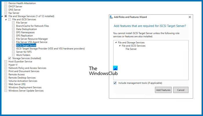
Next, we need to configure the storage that both these servers will be using. That storage server may or may not be a member of the domain, as everything is IP-based. Follow the steps mentioned below to install the File and Storage services for them.
- Open Server Manager.
- Go to Add roles and features.
- Click on Next until you reach the Server Roles tab, expand File and Storage services, look for iSCSI Target Server, tick it, and then and then install it.
Wait for it to complete the installation process. Since we will have only one storage server, you need to install it on a single computer.
3] Enable iSCSI Intiator
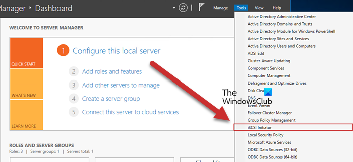
Now, we need to go back to the Failover Cluster nodes and then enable ISCSI Initiator. To do so, click on Tools > iSCSI Initiator in the node server, and then click Yes when prompted to enable the feature. You have to do this to all the servers attached to the node.
Read: How to install and use iSCSI Target to configure Storage Server
4] Configure the Storage Server
We enabled iSCSI Initiator on the node servers to make them accessible to the storage server. Now that we are done with that part, let’s add the nodes to the Storage Server. Follow the steps mentioned below to do so.
- Go to Server Manager > File and Storage Services.
- Click on iSCSI tab.
- Click on Tasks > New iSCSI Virtual disk.
- We can either select a hard drive or just a folder in the server, to do so, click on Type a custom path, then click on Browse, and select either the volume, an existing folder, or create a new folder.
- Click on Next, the virtual disk name, and click on Next.
- Select the size of the disk; Fixed is quicker but Dynamic gives you the flexibility of increasing the size when needed.
- Click on Next, give the target a name, and click on Next.
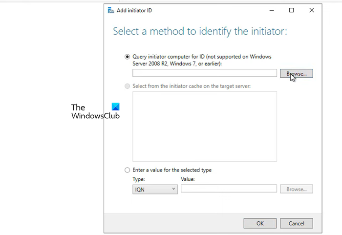
- When you reach the Access Server tab, click on Add.
- Make sure that the Query initiator computer for ID option is checked and click on Browse.
- Enter the name of the node computer and then click on Check names. Add all the nodes of your environment similarly.
- Click on Next.
- Enable CHAP if you want to add authentication between devices.
- Finally, create the connection.
This will create a storage environment consisting of the two nodes.
5] Connect nodes from the initiator back to the target
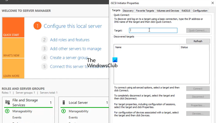
After configuring the storage environment, we can set the target for the initiator. Follow the steps mentioned below to do the same.
- Open Server Manager on the node computer.
- Go to Tools > iSCSI Initiator.
- In the Target field, enter the IP address of the iSCSI Target.
- Click on Quick connect > Ok.
You can go to the Discover tab to see the connection, then go to Volumes and Devices, and see if you can find the volume under the Volume list, if it’s not there, click on Auto Configure.
6] Configure Failover Cluster

Now that we have storage ready, we can just create a cluster and add the two nodes. Follow the steps mentioned below to do the same.
- Open the Server Manager.
- Click on Tools > Failover Cluster Manager.
- This will launch the Failover Cluster Manager utility, so, right-click on the Failover Cluster Manager tab, and click on Create Cluster.
- In the Create cluster wizard, click on Next.
- In the Select Server tab, enter the name of the server and click on Add. You can also browse if you want.
- Run the validation test, once done, click on Next.
- Give the cluster a name and an IP address not currently used. Click Next.
- Finally, click on Next and wait for the cluster creation to complete.
Then, in the upper left-hand corner, you will see that the cluster has been created. To access it, just click on it. Now, you can add roles and storage and make all the required configurations to the cluster.
That’s it!
Read: How to install and configure DNS on Windows Server
How to install Failover Cluster in Windows?
You need to use the Server Manager to install the failover cluster feature in Windows Server. In the Server Manager, go to Add roles and features, and then install the Failover Cluster from the Features tab. For more details, check out the guide above.
Read: How to set up an FTP Server on Windows 11
How to configure Failover Cluster in Windows Server?
To configure failover cluster in Windows Server, you need first install the Failover Cluster feature, configure Storage, create a cluster, and then add the servers. To know more, check out the guide mentioned in this post.
Also Read: Best free Encrypted Cloud Storage Services.
Skip to content
Windows Server 2019 Failover Clustering Types and Uses
One of the powerful features of Windows Server is the ability to create Windows Failover Clusters. With Windows Failover clustering, pools of hardware resources can be bound together in a virtual entity that allows seamlessly hosting resources in a way that is highly available and resilient to failure. Windows Server has certainly evolved over the past several iterations and releases. Now, with Windows Server 2019, Windows Failover Clustering is more powerful than ever and can host many highly available resources for business-critical workloads.
Table of Contents
- Windows Server 2019 Failover Clustering Types and Uses
- Hyper-V Clustering
- Clustering for File Services
- Scale-Out File Server
- Application Layer Clustering
- Host Layer Clustering
- Tiered Clustering
- Concluding Thoughts
Let’s take a look at Windows Server Failover Clustering types and uses for hosting resources.
Windows Server 2019 Failover Clustering Types and Uses
Protect Your Data with BDRSuite
As mentioned earlier, the functionality in the latest version of Windows Server is more capable than ever before with various forms of Windows Failover Clustering functionality able to back multiple types of business-critical services.
Let’s take a look at the following types of Windows Server 2019 Failover Clustering.
- Hyper-V Clustering
- Clustering for File Services
- Scale-Out File Server
- Application Layer Clustering
- Host Layer Clustering
- Tiered Clustering
Each provides tremendous capabilities to ensure production workloads are resilient and highly available.
Hyper-V Clustering

In the realm of virtualization in the enterprise running production workloads, to effectively run Hyper-V in a resilient and highly available fashion, Hyper-V cluster configurations are required. Hyper-V clusters are built on top of Windows Failover Clusters.
How is the Hyper-V cluster architected?
In a traditional Hyper-V cluster, all Hyper-V hosts are connected to shared storage. This allows VMs to reside on storage that all hosts have access to, allowing all hosts to share ownership of the various virtual machines. If a host fails, healthy hosts are able to assume the responsibility of providing compute for the virtual machines assumed from a downed host.
A Hyper-V cluster internally monitors the other Hyper-V hosts so when a host goes down, VMs can be spun up relatively quickly on the healthy hosts. This is done by simply restarting the VMs connected to healthy hosts in the cluster. This highlights the “Failover” in Windows Failover Clustering.
Clustering is not only beneficial when an unforeseen problem arises; it is also beneficial to perform needed maintenance on a Hyper-V host. Using Hyper-V Live Migration, virtual machines can be moved while they are running to different hosts in the Hyper-V cluster to safely evacuate all workloads from a particular host so that maintenance can be performed.
Hyper-V clustering allows for intelligent load balancing for virtual machines running on top of the Hyper-V hosts that make up the Hyper-V Windows Failover Cluster. Much like VMware vSphere’s DRS mechanism, Hyper-V can evaluate Hyper-V hosts and their present load and automatically decide if workloads need to be moved for more efficient placement inside the Hyper-V cluster.
Clustering for File Services
The Clustering for File Services Clustering technology has been around perhaps the longest of any of the other types of clustering use cases. This was one of the original ideas behind clustering technology. This was so that file resources could be made highly available in case a single server failed.
The Clustering for File Services clustering technology works in an active-passive configuration.
Only one file server is active for user connections to files. However, if this active server goes down, the passive server(s) in the cluster will become the active file server that accepts end user connections.
Scale-Out File Server
Traditional Clustering for File Services technology is not robust enough to handle the ever-demanding needs of today’s enterprise, especially considering the storage needs to back virtual machines in a Hyper-V Cluster environment.
As mentioned in the previous section, the Clustering for File Services technology is an active-passive configuration. This is not robust enough for high bandwidth, resiliency, and redundancy requirements of virtual hard disk files. This is where Scale-Out File Server or SOFS comes in.
Scale-Out File Server is designed for hosting high-performance workloads such as Hyper-V storage. SOFS allows supporting the requirements of Hyper-V storage. It does this in an active-active configuration of multiple file servers that have persistent connections between them. If one of the SOFS hosts goes down, another SOFS host picks up the workload without any type of migration or failover process. This allows running Hyper-V virtual machines to stay online even during a failure of an SOFS backing file server host.
Application Layer Clustering
Application Layer Clustering is a feature that can be utilized if a service or application needs to have the most uptime possible, regardless of any hardware failures. As already covered, Hyper-V hosts clustered in a Windows Failover Cluster can restart a VM in the event one of the Hyper-V hosts fails. However, this means any applications the VM is hosting will be unavailable during the time required to restart the VM.
If this time of service interruption, albeit brief, is unacceptable, Application Layer Clustering is certainly an option. Application Layer Clustering can be thought of as “nested” clustering. It involves creating a Windows Failover Cluster using VMs running on top of the physical Windows Failover Cluster hosts. This allows the application to be highly available in addition to the physical Hyper-V hosts backing the Hyper-V Cluster VMs.
Host Layer Clustering
Host Layer Clustering is the general term used to describe the technology we have already referred to when talking about Hyper-V Clustering. This is the clustering of the physical Windows Server Failover hosts. This allows clustering two or more physical servers using the Windows Failover Clustering technology to make various roles highly available. Notable among these in today’s production data centers is the Hyper-V role.
Windows Server 2019 Hyper-V Cluster
Tiered Clustering
When it comes to production workloads, generally the component that matters the most to end users or business stakeholders is the application. However, to ensure that application is resilient and redundant, a tiered clustering approach can be used where both a combination of Host Layer Clustering and Application Layer Clustering are used to ensure both the VM is resilient and redundant (host layer clustering) and the application itself is resilient and redundant (application layer clustering). This allows providing the most resilient configuration possible to ensure the most uptime and high availability for business-critical workloads.
Concluding Thoughts
Clustering technology has certainly evolved from the early days with legacy versions of Windows Server. Windows Server 2019 Failover Clustering types and uses have certainly expanded the various applications of Windows Server Failover Clustering technology and broadened its scope in the enterprise.
Today’s business-critical workloads are required to be more and more resilient and redundant to support “always on” infrastructure driving today’s very web-centric businesses. Windows Server 2019 Failover Clustering supports these new and demanding use cases with a combination of various cluster types and applications of clustering technologies.
BDRSuite offers robust Windows backup solutions to secure your data and ensure data integrity. Explore its features and benefits for Windows backup today.
Follow our Twitter and Facebook feeds for new releases, updates, insightful posts and more.
Try BDRSuite for Free!
Schedule a live demo with one of our product experts
Start your full-featured 30-day free trial
Explore detailed pricing, editions & features
In this blog, we will take a look at how to create a two-node failover cluster configuration running Windows Server 2022 with a few shared disks mapped from our ISCSI san.
Blog Series
- Create/Add a Raw Device Mapping (P-RDM) to a VM Cluster
- SQL Server Failover Cluster Installation
- Expand a Virtual and Physical RDM LUN
- How to Set Up and Configure Failover Cluster On Windows Server 2022
A failover cluster feature on Windows Server allows us to group a couple of servers into a single failover cluster thus providing higher resiliency, scalability and high availability for your backend servers.
Windows Server 2022 can provide cluster configuration for key services like ;
- File Server
- DFS Namespace Server
- DHCP Server
- iSNS Server
- iSCSI Target Server
- Distributed Transaction Coordinator (DTC)
- Hyper-V Replica Broker
- Message Queuing
- WINS Server
Summary of Windows 2019/2022 Failover Cluster Deployment
The following are the high-level steps required for our Windows Cluster deployment.
- Deploy two Windows 2022 VM
- Finish all Windows Updates
- Join the domain if needed. This isn’t a mandatory requirement.
- Each VM will have two network interfaces –
- Management/Production Network
- Cluster Network
- Add 3 DNS records
- Primary Server
- Secondary Server
- Cluster Server Name ( VIP )
- Attach the same ISCSI disk/lun to the primary server & secondary server.
- Virtual disk formats should be thick provisioned eager zeroed.
- Install Failover clustering role on both servers
- Bring the disk online via computer management on the primary server.
- Run readiness check prior to joining them as a cluster
- Once passed, join nodes to the cluster
- Add roles if needed.
Management VM Sizing Requirements
| VM | IP Address |
| Primary – Production / Mgmt Network | 172.16.11.199 |
| Primary – Cluster Network | 172.16.99.199 |
| Secondary – Production / Mgmt Network | 172.16.11.200 |
| Primary – Cluster Network | 172.16.99.200 |
| Clustered Server Name – Production / Mgmt Network | 172.16.11.201 |
Add DNS records for the VM’s

Open Server Manager on both servers and install the Failover Cluster feature or we can also install this feature using the PowerShell command:
Install-WindowsFeature Failover-Clustering –IncludeManagementTools

You can install the same via the GUI by selecting failover clustering

Click Next to Continue

Choose Role Based Installation

Choose the server you wish to install the services on

Under Server Roles, we will click Next to continue

Under Features to be added select Failover Clustering

Click Install to begin the installation

Confirm if the installation has succeeded.

After a successful installation, it appears in the Server Manager, click Tools, and then Failover Cluster Manager.

In the next step, we will map an ISCSI Lun to both the servers . Both servers are mapped with the same ISCSI 10 GB lun

Likewise on the second VM, we’ve mapped the same lun

Failover Cluster readiness check on Primary
We will need to bring the disk online in one server and initialize the disk, however, we don’t need to do this process on the second server as it’s taken care of by the cluster configuration.
Let’s begin with the configuration on node 1.
Under computer management, we will select the disk and initialise the disk.

Choose the disk and Initialise the disk to create a new volume from the disk provisioned.

Click Next to continue

Choose a drive letter
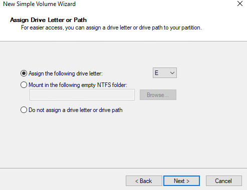
Give the Volume a name

Finally, complete the wizard

Our volume is ready

Failover Cluster readiness check on Primary
So far we have mapped two nic’s to both servers, added the same ISCSI lun on both servers, formatted and got a volume up on one server.
Let’s verify if everything is set up correctly.
In Server Manager click Tools and Click Failover Cluster Manager.
Under the Action menu click Validate Configuration.
Click Next.
Select the browse button.
Type name both the servers and click ok.

31- After Selecting the two-node servers for validation, click next.

Select Run all tests and click Next
Review the configuration and click next.

Cluster validation tests will take a while

If errors are encountered, correct them before you proceed. Once validation completes, view the report and click Finish to continue
Create a Failover Cluster Server in Windows 2022
Under Action Menu so, select Create Cluster.
Click Next.
Click the browse button and search for our servers
Add both servers into the selection list

Give the cluster a name, select the IP address and click next.

Click next to continue and wait

Cluster setup will take a while
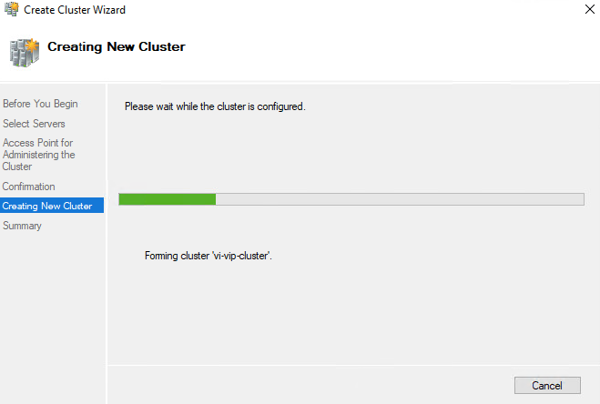
Once done, click Finish

Verify the DNS Configuration and we can now see a VIP AD object being added for the cluster

Verify if the VIP address is pingable.

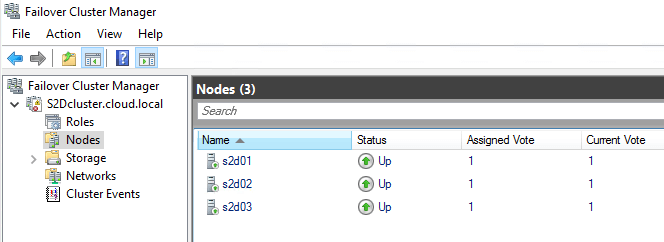
Both the Nodes are up now.

Under the Storage section, we can see disks being mapped

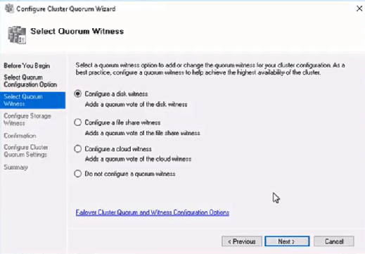
You can configure the quorum witness mode by right-clicking the cluster name and selecting More Actions > Configure Cluster Quorum Settings.
The presence of a quorum in a cluster for its proper operation is determined by the majority of voting members who are active members of the cluster.
To ensure correct operation of the cluster, you need to configure the quorum. By default, each cluster node has one quorum vote. In addition, a quorum witness (if configured) has one additional quorum vote. You can configure one quorum witness for each cluster. Each item can cast one vote to determine if a cluster can be started.
If there is a number of nodes in the cluster, you will need to configure the quorum witness resource. In Windows Server 2019/2022, you can use as a witness resource.
- File Share witness — (shared SMB folder);
- Disk Witness — shared disk (with simultaneous access to it from all nodes);
- Cloud Witness — cloud disk resource in Azure (Blob storage).

Adding Roles for Cluster
Now that our failover cluster is defined, we can add roles for any of these services as needed. Click Configure Role to add a service or role in HA mode.
Click Next to proceed

Choose the service you wish to configure High availability

References
https://docs.microsoft.com/en-us/answers/questions/589879/server-2022-cluster-validation-network-invalid-nam.html
(Visited 4,952 times, 2 visits today)
Время на прочтение13 мин
Количество просмотров44K
Автор статьи – Роман Левченко (www.rlevchenko.com), MVP – Cloud and Datacenter Management
Всем привет! Совсем недавно была объявлена глобальная доступность Windows Server 2016, означающая возможность уже сейчас начать использование новой версии продукта в Вашей инфраструктуре. Список нововведений довольно обширный и мы уже описывали часть из них (тут и тут), но в этой статье разберем службы высокой доступности, которые, на мой взгляд, являются самыми интересными и используемыми (особенно в средах виртуализации).

Cluster OS Rolling upgrade
Миграция кластера в прошлых версиях Windows Server является причиной значительного простоя из-за недоступности исходного кластера и создания нового на базе обновленной ОС на узлах с последующей миграцией ролей между кластерами. Такой процесс несет повышенные требования к квалификации персонала, определенные риски и неконтролируемые трудозатраты. Данный факт особенно касается CSP или других заказчиков, которые имеют ограничения по времени недоступности сервисов в рамках SLA. Не стоит описывать, что для поставщика ресурсов означает значительное нарушение SLA )
Windows Server 2016 ситуацию исправляет через возможность совмещения Windows Server 2012 R2 и Windows Server 2016 на узлах в рамках одного кластера во время его апгрейда (Cluster OS Rolling Upgrade (далее CRU)).

Из названия можно догадаться, что процесс миграции кластера заключается в основном в поэтапной переустановке ОС на серверах, но об этом поговорим подробнее чуть позже.
Определим сначала список «плюшек», которые CRU предоставляет:
- Полное отсутствие простоя при апгрейде кластеров WS2012R2 Hyper-V/SOFS. Для других кластерных ролей (к примеру, SQL Server) возможна их недоступность (менее 5 минут), необходимая для отработки разового failover.
- Нет необходимости в дополнительном аппаратном обеспечении. Как правило, кластер строится из учета возможной недоступности одного или нескольких узлов. В случае с CRU, недоступность узлов будет планируемой и поэтапной. Таким образом, если кластер может безболезненно пережить временное отстутствие хотя бы 1 из узлов, то для достижения zero-downtime дополнительных узлов не требуется. Если планируется апгрейд сразу нескольких узлов (это поддерживается), то необходимо заранее спланировать распределение нагрузки между доступными узлами.
- Создание нового кластера не требуется. CRU использует текущий CNO.
- Процесс перехода обратим (до момента повышения уровня кластера).
- Поддержка In-Place Upgrade. Но, стоит отметить, что рекомендуемым вариантом обновления узлов кластера является полноценная установка WS2016 без сохранения данных (clean-os install). В случае с In-Place Upgrade обязательна проверка полной функциональности после обновления каждого из узлов (журналы событий и т.д.).
- CRU полностью поддерживается VMM 2016 и может быть автоматизирован дополнительно через PowerShell/WMI.
Процесс CRU на примере 2-х узлового кластера Hyper-V:
- Рекомендуется предварительное резервное копирование кластера (БД) и выполняемых ресурсов. Кластер должен быть в работоспособном состоянии, узлы доступны. При необходимости следует исправить имеющиеся проблемы перед миграцией и приостановить задачи резервного копирования перед стартом перехода.
- Обновить узлы кластера Windows Server 2012 R2, используя Cluster Aware Updating (CAU) или вручную через WU/WSUS.
- При имеющемся настроенном CAU необходимо временное его отключение для предотвращения его возможного воздействия на размещение ролей и состояния узлов во время перехода.
- CPU на узлах должны иметь поддержку SLAT для поддержки выполнения виртуальных машин в рамках WS2016. Данное условие является обязательным.
- На одном из узлов выполняем перенос ролей (drain roles) и исключение из кластера (evict):
- После исключения узла из кластера выполняем рекомендуемую полную установку WS2016 (clean OS install, Custom: Install Windows only (advanced))
- После переустановки верните сетевые параметры обратно*, обновите узел и установите необходимые роли и компоненты. В моем случае требуется наличие роли Hyper-V и, конечно, Failover Clustering.
New-NetLbfoTeam -Name HV -TeamMembers tNIC1,tNIC2 -TeamingMode SwitchIndependent -LoadBalancingAlgorithm DynamicAdd-WindowsFeature Hyper-V, Failover-Clustering -IncludeManagementTools -RestartNew-VMSwitch -InterfaceAlias HV -Name VM -MinimumBandwidthMode Weight -AllowManagementOS 0* использование Switch Embedded Teaming возможно только после полного завершения перехода на WS2016.
- Добавьте узел в соответствующий домен.
Add-Computer -ComputerName HV01 -DomainName domain.com -DomainCredential domain\rlevchenko - Возвращаем узел в кластер. Кластер начнет работать в смешанном режиме поддержки функциональности WS2012R2 без поддержки новых возможностей WS2016. Рекомендуется завершить обновление оставшихся узлов в течение 4 недель.
- Перемещаем кластерные роли обратно на узел HV01 для перераспределения нагрузки.
- Повторяем шаги (4-9) для оставшейся ноды (HV02).
- После обновления узлов до WS2016 необходимо поднять функциональный уровень (Mixed Mode – 8.0, Full – 9.0) кластера для завершения миграции.
PS C:\Windows\system32> Update-ClusterFunctionalLevel
Updating the functional level for cluster hvcl.
Warning: You cannot undo this operation. Do you want to continue?
[Y] Yes [A] Yes to All [N] No [L] No to All [S] Suspend [?] Help (default is Y): aName
— Hvcl - (опционально и с осторожностью) Обновление версии конфигурации ВМ для включения новых возможностей Hyper-V. Требуется выключение ВМ и желателен предварительный бекап. Версия ВМ в 2012R2 – 5.0, в 2016 RTM – 8.0.В примере показана команда для обновления всех ВМ в кластере:
Get-ClusterGroup|? {$_.GroupType -EQ "VirtualMachine"}|Get-VM|Update-VMVersionПеречень версий ВМ, поддерживаемые 2016 RTM:


Cloud Witness
В любой кластерной конфигурации необходимо учитывать особенности размещения Witness для обеспечения дополнительного голоса и общего кворума. Witness в 2012 R2 может строиться на базе общего внешнего файлового ресурса или диска, доступных каждому из узлов кластера. Напомню, что необходимость конфигурации Witness рекомендована при любом количестве узлов, начиная с 2012 R2 (динамический кворум).
В Windows Server 2016 для обеспечения возможности построения DR на базе Windows Server и для других сценариев доступна новая модель кворумной конфигурации на базе Cloud Witness.
Cloud Witness использует ресурсы Microsoft Azure (Azure Blob Storage, через HTTPS, порты на узлах должны быть доступны) для чтения/записи служебной информации, которая изменяется при смене статуса кластерных узлов. Наименование blob-файла производится в соответствии с уникальным идентификатором кластера, — поэтому один Storage Account можно предоставлять нескольким кластерам сразу (1 blob-файл на кластер в рамках создаваемого автоматически контейнера msft-cloud-witness). Требования к размеру облачного хранилища минимальны для обеспечения работы witness и не требует больших затрат на его поддержку. Так же размещение в Azure избавляет от необходимости третьего сайта при конфигурации Stretched Cluster и решения по его аварийному восстановлению.
Cloud Witness может применяться в следующих сценариях:
- Для обеспечения DR кластера, размещенного в разных сайтах (multi-site).
- Кластеры без общего хранилища (Exchange DAG, SQL Always-On и другие).
- Гостевые кластеры, выполняющиеся как в Azure, так и в on-premises.
- Кластеры хранения данных с или без общего хранилища (SOFS).
- Кластеры в рамках рабочей группы или разных доменах (новая функциональность WS2016).
Процесс создания и добавления Cloud Witness достаточно прост:
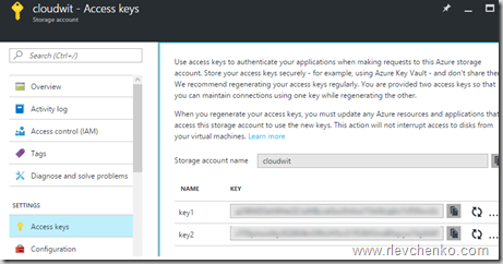
- Создайте новый Azure Storage Account (Locally-redundant storage) и в свойствах аккаунта скопируйте один из ключей доступа.
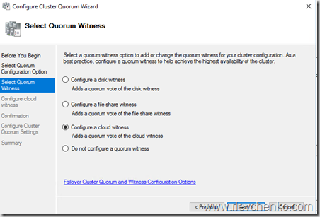
- Запустите мастер настройки кворумной конфигурации и выберите Select the Quorum Witness – Configure a Cloud Witness.
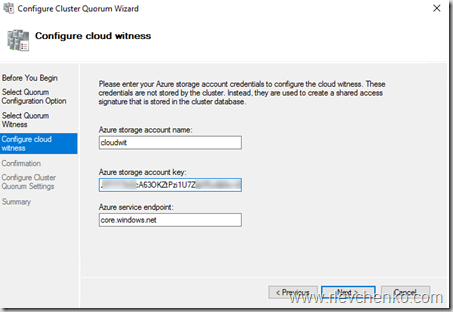
- Введите имя созданного storage account и вставьте ключ доступа.
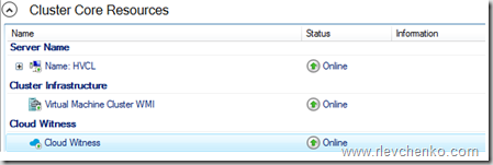
- После успешного завершения мастера конфигурации, Witness появится в Core Resources.
- Blob-файл в контейнере:
Для упрощения можно использовать PowerShell:


Workgroup and Multi-Domain Clusters
В Windows Server 2012 R2 и предыдущих версиях необходимо соблюдение глобального требования перед созданием кластера: узлы должны быть членами одного и того же домена. Active Directory Detached кластер, презентованный в 2012 R2, имеет подобное требование и не упрощает его существенным образом.
В Windows Server 2016 возможно создание кластера без привязки к AD в рамках рабочей группы или между узлами, являющиеся членами разных доменов. Процесс схож с созданием deattached -кластера в 2012 R2, но имеет некоторые особенности:
- Поддерживается только в рамках среды WS2016.
- Требуется роль Failover Clustering.
Install-WindowsFeature Failover-Clustering -IncludeManagementTools - На каждом из узлов требуется создать пользователя с членством в группе Administrators или использовать built-in уч. запись. Пароль и наименование пользователя должны быть идентичны.
net localgroup administrators cluadm /addПри появлении ошибки “Requested Registry access is not allowed” необходимо изменить значение политики LocalAccountTokenFilterPolicy.
New-ItemProperty -Path HKLM:\SOFTWARE\Microsoft\Windows\CurrentVersion\Policies\System -Name LocalAccountTokenFilterPolicy -Value 1 - Primary DNS -suffix на узлах должен быть определен.
- Создание кластера поддерживается как через PowerShell, так и через GUI.
New-Cluster -Name WGCL -Node rtm-1,rtm-2 -AdministrativeAccessPoint DNS -StaticAddress 10.0.0.100 - В качестве Witness возможно использование только Disk Witness или описанный ранее Cloud Witness. File Share Witness, к сожалению, не поддерживается.


Поддерживаемые сценарии использования:
| Роль | Статус поддержки | Комментарий |
|---|---|---|
| SQL Server | Поддерживается | Рекомендуется использовать встроенную аутентификацию SQL Server |
| File Server | Поддерживается, но не рекомендуется | Отсутствие Kerberos аутентификации, являющейся основной для SMB |
| Hyper-V | Поддерживается, но не рекомендуется | Доступна только Quick Migration. Live Migration не поддерживается |
| Message Queuing (MSMQ) | Не поддерживается | MSMQ требуется ADDS |
Virtual Machine Load Balancing / Node Fairness
Динамическая оптимизация, доступная в VMM, частично перекочевала в Windows Server 2016 и предоставляет базовое распределение нагрузки на узлах в автоматическом режиме. Для перемещения ресурсов используется Live Migration и эвристики, на базе которых кластер каждые 30 минут решает проводить балансировку или нет:
- Текущий % использования памяти на узле.
- Средняя загрузка по CPU в 5 минутном интервале.
Предельные допустимые значения загрузки определяются значением AutoBalancerLevel:
get-cluster| fl *autobalancer*
AutoBalancerMode  : 2
AutoBalancerLevel : 1
| AutoBalancerLevel | Агрессивность балансировки | Комментарий |
|---|---|---|
| 1 (по умолчанию) | Low | Осуществлять балансировку при загрузке узла более 80% по одной из эвристик |
| 2 | Medium | При загрузке более 70% |
| 3 | High | При загрузке более 60% |
Параметры балансировщика можно определить и в GUI (cluadmin.msc). По умолчанию, используется Low уровень агрессивности и режим постоянной балансировки.
Для проверки я использую следующие параметры:
AutoBalancerLevel: 2
(Get-Cluster).AutoBalancerLevel = 2AutoBalancerMode: 2
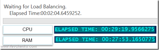
(Get-Cluster).AutoBalancerMode = 2Имитируем нагрузку сначала по CPU (около 88%) и затем по RAM (77%). Т.к. определен средний уровень агрессивности при принятии решения о балансировке и наши значения по загрузке выше определенного значения (70%) виртуальные машины на загруженном узле должны переехать на свободный узел. Скрипт ожидает момент живой миграции и выводит затраченное время (от точки начала загрузки на узла до осуществления миграции ВМ).
В случае с большой нагрузкой по CPU балансировщик переместил более 1 ВМ, при нагрузке RAM – 1 ВМ была перемещена в рамках обозначенного 30 минутного интервала, в течение которого происходит проверка загрузки узлов и перенос ВМ на другие узлы для достижения <=70% использования ресурсов.
При использовании VMM встроенная балансировка на узлах автоматически отключается и заменяется на более рекомендуемый механизм балансировки на базе Dynamic Optimization, который позволяет расширенно настроить режим и интервал выполнения оптимизации.
Virtual machine start ordering
Изменение логики старта ВМ в рамках кластера в 2012 R2 строится на понятии приоритетов (low,medium,high), задача которых обеспечивать включение и доступность более важных ВМ перед запуском остальных «зависимых» ВМ. Обычно это требуется для multi-tier сервисов, построенных, к примеру, на базе Active Directory, SQL Server, IIS.
Для повышения функциональности и эффективности в Windows Server 2016 добавлена возможность определять зависимости между ВМ или группами ВМ для решения обеспечения корректного их старта, используя Set или наборы кластерных групп. Преимущественно нацелены на использование совместно с ВМ, но могут быть использованы и для других кластерных ролей.
Для примера используем следующий сценарий:
1 ВМ Clu-VM02 является приложением, зависимым от доступности Active Directory, выполняемой на вирт. машине Clu-VM01. А ВМ Clu-VM03, в свою очередь, зависит от доступности приложения, расположенного на ВМ Clu-VM02.
Создадим новый set, используя PowerShell:
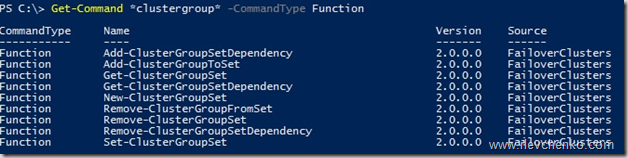
ВМ с Active Directory:
PS C:\> New-ClusterGroupSet -Name AD -Group Clu-VM01
Name: AD
GroupNames: {Clu-VM01}
ProviderNames: {}
StartupDelayTrigger: Delay
StartupCount: 4294967295
IsGlobal: False
StartupDelay: 20
Приложение:
New-ClusterGroupSet -Name Application -Group Clu-VM02
Зависимый сервис от приложения:
New-ClusterGroupSet -Name SubApp -Group Clu-VM03
Добавляем зависимости между set’ами:
Add-ClusterGroupSetDependency -Name Application -Provider AD
Add-ClusterGroupSetDependency -Name SubApp -Provider Application
В случае необходимости можно изменить параметры set’а, используя Set-ClusterGroupSet. Пример:
Set-ClusterGroupSet Application -StartupDelayTrigger Delay -StartupDelay 30StartupDelayTrigger определяет действие, которое необходимо произвести после старта группы:
- Delay – ожидать 20 секунд (по умолчанию). Используется совместно с StartupDelay.
- Online – ожидать состояния доступности группы в set.
StartupDelay – время задержки в секундах. 20 секунд по умолчанию.
isGlobal – определяет необходимость запуска set’а перед стартом других наборов кластерных групп (к примеру, set с группами ВМ Active Directory должен быть глобально доступен и, следовательно, стартовать раньше других коллекций).
Попробуем стартовать ВМ Clu-VM03:
Происходит ожидание доступности Active Directory на Clu-VM01 (StartupDelayTrigger – Delay, StartupDelay – 20 секунд)

После запуска Active Directory происходит запуск зависимого приложения на Clu-VM02 (StartupDelay применяется и на этом этапе).

И последним шагом является запуск самой ВМ Clu-VM03.

VM Compute/Storage Resiliency
В Windows Server 2016 появились новые режимы работы узлов и ВМ для повышения степени их устойчивости в сценариях проблемного взаимодействия между кластерными узлами и для предотвращения полной недоступности ресурсов за счет реакции на «малые» проблемы перед возникновением более глобальных (проактивное действие).
Режим изоляции (Isolated)
На узле HV01 внезапно стала недоступна служба кластеризации, т.е. у узла появляются проблемы интра-кластерного взаимодействия. При таком сценарии узел помещается в состояние Isolated (ResiliencyLevel) и временно исключается из кластера.

Виртуальные машины на изолированном узле продолжают выполняться* и переходят в статус Unmonitored (т.е. служба кластера не «заботится» о данных ВМ).
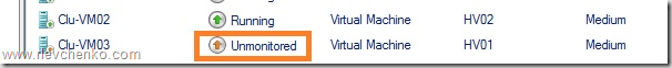
*При выполнении ВМ на SMB: статус Online и корректное выполнение (SMB не требует «кластерного удостоверения» для доступа). В случае с блочным типом хранилища ВМ уходят статус Paused Critical из-за недоступности Cluster Shared Volumes для изолированного узла.
Если узел в течение ResiliencyDefaultPeriod (по умолчанию 240 секунд) не вернет службу кластеризации в строй (в нашем случае), то он переместит узел в статус Down.
Режим карантина (Quarantined)
Предположим, что узел HV01 успешно вернул в рабочее состояние службу кластеризации, вышел из Isolated режим, но в течение часа ситуация повторилась 3 или более раза (QuarantineThreshold). При таком сценарии WSFC поместит узел в режим карантина (Quarantined) на дефолтные 2 часа (QuarantineDuration) и переместит ВМ данного узла на заведомо «здоровый».


При уверенности, что источник проблем был ликвидирован, можем ввести узел обратно в кластер:
Важно отметить, что в карантине одновременно могут находиться не более 25% узлов кластера.
Для кастомизации используйте вышеупомянутые параметры и cmdlet Get-Cluster:
(Get-Cluster). QuarantineDuration = 1800Storage Resiliency
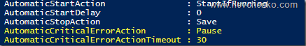
В предыдущих версиях Windows Server отработка недоступности r/w операций для вирт. диска (потеря соединения с хранилищем) примитивная – ВМ выключаются и требуется cold boot на последующем старте. В Windows Server 2016 при возникновении подобных проблем ВМ переходит в статус Paused-Critical (AutomaticCriticalErrorAction), предварительно «заморозив» своё рабочее состояние (её недоступность сохранится, но неожиданного выключения не будет).
При восстановлении подключения в течение таймаута (AutomaticCriticalErrorActionTimeout, 30 минут по умолчанию), ВМ выходит из paused-critical и становится доступной с той «точки», когда проблема была идентифицирована (аналогия – pause/play).
Если таймаут будет достигнут раньше возвращения хранилища в строй, то произойдет выключение ВМ (действие turn off)
Site-Aware/Stretched Clusters и Storage Replica
Тема, заслуживающая отдельного поста, но постараемся кратко познакомиться уже сейчас.
Ранее нам советовали сторонние решения (много $) для создания полноценных распределенных кластеров (обеспечение SAN-to-SAN репликации). С появлением Windows Server 2016 сократить бюджет в разы и повысить унификацию при построении подобных систем становится действительностью.
Storage Replica позволяет осуществлять синхронную (!) и асинхронную репликацию между любыми системами хранения (включая Storage Spaces Direct) и поддерживающая любые рабочие нагрузки, — лежит основе multi-site кластеров или полноценного DR -решения. SR доступна только в редакции Datacenter и может применяться в следующих сценариях:

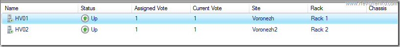
Использование SR в рамках распределенного кластера особенно ещё наличием автоматической отработки по отказу и тесной работы с site-awareness, который был презентован так же в Windows Server 2016. Site-Awarieness позволяет определять группы узлов кластера и привязывать их к физическому месторасположению (site fault domain/сайт) для формирования кастомных политик отказа (failover), размещения данных Storage Spaces Direct и логики распределения VM. Кроме того, возможна привязка не только на уровне сайтов, но и на более низкие уровни (node, rack, chassis).

New-ClusterFaultDomain –Name Voronezh –Type Site –Description “Primary” –Location “Voronezh DC”
New-ClusterFaultDomain –Name Voronezh2 –Type Site –Description “Secondary” –Location “Voronezh DC2”
New-ClusterFaultDomain -Name Rack1 -Type Rack
New-ClusterFaultDomain -Name Rack2 -Type Rack
New-ClusterFaultDomain -Name HPc7000 -type Chassis
New-ClusterFaultDomain -Name HPc3000 -type Chassis
Set-ClusterFaultDomain –Name HV01 –Parent Rack1
Set-ClusterFaultDomain –Name HV02 –Parent Rack2
Set-ClusterFaultDomain Rack1,HPc7000 -parent Voronezh
Set-ClusterFaultDomain Rack2,HPc3000 -parent Voronezh2
Такой подход в рамках мульти-сайт кластера несет следующие плюсы:
- Отработка Failover первоначально происходит между узлами в рамках Fault домена. Если все узлы в Fault Domain недоступны, то только тогда переезд на другой.
- Draining Roles (миграция ролей при режиме обслуживания и т.д.) проверяет возможность переезда сначала на узел в рамках локального сайта и только потом перемещает их на иной.
- Балансировка CSV (перераспределение кластерных дисков между узлами) так же будет стремиться отрабатывать в рамках родного fault-домена/сайта.
- ВМ будут стараться располагаться в том же сайте, где и их зависимые CSV. Если CSV мигрируют на другой сайт, то ВМ через 1 минуту начнут свою миграцию на тот же сайт.
Дополнительно, используя логику site-awareness, возможно определение «родительского» сайта для всех вновь создаваемых ВМ/ролей:
(Get-Cluster).PreferredSite = <наименование сайта>Или настроить более гранулярно для каждой кластерной группы:
(Get-ClusterGroup -Name ИмяВМ).PreferredSite = <имя предпочтительного сайта>Другие нововведения
- Поддержка Storage Spaces Direct и Storage QoS.
- Изменение размера shared vhdx для гостевых кластеров без простоя, поддержка Hyper-V репликации и рез. копирования на уровне хоста.
- Улучшенная производительность и масштабирование CSV Cache с поддержкой tiered spaces, storage spaces direct и дедупликации (отдать десятки ГбБ RAM под кеш – без проблем).
- Изменения в формировании журналов кластера (информация о временном поясе и т.д.) + active memory dump (новая альтернатива для full memory dump) для упрощения диагностирования проблем.
- Кластер теперь может использовать несколько интерфейсов в рамках одной и той же подсети. Конфигурировать разные подсети на адаптерах не требуется для их идентификации кластером. Добавление происходит автоматически.
На этом наш обзорный тур по новым функциям WSFC в рамках Windows Server 2016 завершен. Надеюсь, что материал получился полезным. Спасибо за чтение и комментарии.
Отличного всем дня!