
How to configure Windows DHCP for Avaya IP telephones(Compliments of Kyle L Holladay, Sr, R.I.P.)
In this example we will configure Windows DHCP for Avaya IP telephones. In addition to your standard Option 003 Router you will also need a custom scope option in order for an Avaya IP phone to boot properly using DHCP. While I do reference the IP Office in this document the content is not specific to the IP Office. Options 176 and 242 are common to all Avaya IP telephones and this method would work equally well for phones connected back the an Avaya Aura or Avaya Communication Manager (aka ACM or CM)
1. Open the DHCP MMC under Control Panel>Administrative Tools>DHCP
2. Right click on the DHCP server name at the top of the tree on the left side of the screen immediately under “DHCP” and select “Set Predefined Options”.
3. Click on the [Add] button.
4. (Avaya 4600 & 5600 series IP phones) Under Name enter “Avaya Option 176” and select a Data type of “String” and a Code of “176” then click [OK].
5. (Avaya 1600 and 9600 series IP phones) Repeat step 4 above to add option 242. Under Name enter “Avaya Option 242” and select a Data Type of “String” and a Code of “242” then click [OK].
From this point on things will change if you are using a single VLAN for both Voice and Data or two separate VLANs… I will cover both.
We will assume your IP Office is using the default IP address of 192.168.42.1 (modify to match your IP Office’s actual IP address).
********** If using only a single VLAN for both Voice and Data **********
1. Expand our your DHCP scope and right click “Scope Options” and select “Configure Options”
2. Scroll down and locate option(s) 176 and/or 242. Under “String value” enter the following:
Remember to replace the 192.168.42.1 with the actual IP address of your IP Office
| Option 176 | MCIPADD=192.168.42.1,MCPORT=1719,TFTPSRVR=192.168.42.1 |
| Option 242 | MCIPADD=192.168.42.1,MCPORT=1719,HTTPSRVR=192.168.42.1 |
>>>>>>>>>>>>>>>>>>>> OR <<<<<<<<<<<<<<<<<<<<
********** If using a separate VLAN for Voice and Data (we will use “11” for the Voice VLAN tag in this example) **********
1. Expand out your DATA DHCP Scope and right click on “Scope Options” and select “Configure Options”
2. Scroll down and locate option(s) 176 and/or 242. Under “String value” enter the following:
| Both Option 176 & 242 | L2Q=1,L2QVLAN=11,VLANTEST=0 |
3. Expand out your VOICE DHCP Scope and right click on “Scope Options” select “Configure Options”
2. Scroll down and locate option(s) 176 and/or 242. Under “String value” enter the following:
Remember to replace the 192.168.42.1 with the actual IP address of your IP Office
| Option 176 | MCIPADD=192.168.42.1,MCPORT=1719,TFTPSRVR=192.168.42.1,VLANTEST=0 |
| Option 242 | MCIPADD=192.168.42.1,MCPORT=1719,HTTPSRVR=192.168.42.1,VLANTEST=0 |
(NOTE: There are many other values that can be entered under your option 176 and option 242 such as L2QAUD and L2QSIG but those can just as easily be set in your 46xxsettings.txt file)
The final step is to configure the IP Office to handle the TFTP/HTTP requests. Your best option is to use a standard Compact Flash card inserted into the Embedded Voicemail slot or the Embedded Voicemail Card itself to hold your .bin, .txt and .scr files. The alternative is to use Manager or some other TFTP/HTTP server running on a PC to serve up the needed files. Here are examples of both
When using a Compact Flash card or Embedded Voicemail card to hold the files internal to the IP Office
Set the “TFTP Server IP Address” and the “HTTP Server IP Address” to the IP Office’s own IP address. This will tell the unit to look to itself to handle all file requests.
When using an external TFTP server such as IP Office Manager
Set the “TFTP Server IP Address” to the IP Address of the PC running Manager but leave the HTTP address blank. The IP Office will relay all incoming TFTP requests and proxy all incoming HTTP requests as TFTP. This eliminates the need to setup both a TFTP and HTTP server on the target PC.
Discover more from IP Office Assistance
Subscribe to get the latest posts sent to your email.
We have had more issues lately with voice VLAN and Lync than anything else. It has been a major pain. Part of our problem is that there is an issue with Cisco 6500 switches and Lync’s LLDP implementation. We opened up cases with Microsoft and Cisco and suffice it to say, we are still trying to get a resolution, but that is a whole other post.
So as a Plan B, we needed to setup DHCP so that we could drop Lync Phone devices into a voice VLAN (and not use up precious data VLAN IPs). First off, if you are running Microsoft’s DHCP server, don’t bother reading this. Go immediately to Jeff Schertz’s excellent article on setting it up:
Now, if you are still reading this, you are probably in the same boat we were in – you are running a non-Microsoft DHCP server. Unfortunately there was little to no documentation on setting this up and Jeff’s article was good, but didn’t give us the options and configuration info we needed. So, we decided to put up a Microsoft DHCP server and do some wireshark captures and finally came accross the settings that we needed. Now Lync phone devices will use one of two vendor classes. First, it tries CPE-OCPHONE, which is the legacy one that Tanjay devices use. Second, it tries MS-UC-Client, which is the new aries one. When we had orginally setup our DHCP settings for Lync devices and PIN based authenticaiton, we created and configured the MS-UC-Client vendor class. Since that was working already and since the CPE-OCPHONE class is used first, we decided to create that new vendor class for the purposes of configuring the voice VLAN. We also didn’t want to mess with concatenating the options for the voice VLAN into the rest of our settings.
So, first step is to create a new DHCP vendor class. We kept the Display name and description that Jeff used, but it is the data part that is important to keep the same.
Display Name MSCPEClient
Description UC Vendor Class Id
ASCII Data CPE-OCPHONE
Now this is the part that we didn’t know what value was needed. It is using option 43, which is 2b in Hex and has a length of 4 (2b04). The value that needs to be defined is option 10 (0a in Hex) and a length of 2 (02 in Hex). Now we were testing with a voice VLAN ID of 800 (0320 in Hex). So the entire value was this: 0a020320. If you are using another VLAN ID, than just replace the last part with your ID number. That value made all the difference. It seems like we tried almost every combination of values when we tried to get this to work, so we were relieved when we finally got the correct info. Hope this helps other people in the same bind as we were.
About victorucblog
I am the Windows Team Lead at Marquette University.
This entry was posted in Uncategorized and tagged DHCP, Lync, Lync Phone Edition, VLAN. Bookmark the permalink.
Contents
Introduction
In an optimized IP Telephony network, IP addresses for telephones and PCs must be set up in different network segments. If Dynamic Host Configuration Protocol (DHCP) is used to assign addresses, then a DHCP server for each network segment is normally needed. However, you can use a single DHCP server to assign both ranges of addresses if you have routers capable of DHCP relay in your IP network. This document explains how and why it is possible to use a single server for both voice and data IP addresses.
Note: The information in this document does not apply in a fully switched network or if you do not have a routing capable device. In such scenarios, there are only two possibilities for assigning different IP addresses to telephones and PCs.You must either have a DHCP server with two network interface cards or have two DHCP servers.
Prerequisites
Requirements
There are no specific requirements for this document.
Components Used
This document is not restricted to specific software and hardware versions.
Conventions
For more information on document conventions, refer to the Cisco Technical Tips Conventions.
Problem
If you install an IP Telephony network, then you must assign IP addresses for your telephones and PCs in different network segments. These address assignments require a DHCP server for each network segment. However, you have only one DHCP server.
Solution
To be able to use your current DHCP server to assign addresses for both VLANs, you must have a Layer 3 (L3) device in the network that can do do the inter-VLAN routing.
The two examples in this document describe how to use one DHCP server to assign both voice and data IP addresses.
The Network Setup
There is a current network with a Cisco Catalyst 6000 or a Catalyst 3524-XL-PWR. In which, VLAN 10 is configured to be the data VLAN used by the PCs and servers. In the same VLAN there is also a DHCP server that runs Windows 2000 to provide addresses in the range 10.10.10.20 to 10.10.10.200. The DHCP server IP address is 10.10.10.2.
To add IP Telephony in this network, plug an IP phone with a PC in the back to the Catalyst port where the PC was connected.
Example of Catalyst 6000 with MSFC
In this scenario, there is a Cisco Catalyst 6000 with a Multilayer Switch Feature Card (MSFC) as the routing capable device.
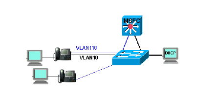
To allow the PC and telephone to be on the same Catalyst port, you need to configure the auxiliaryVLAN command with the new voice VLAN 110 as shown:
cat6k-access> (enable) set VLAN 110 name 11.1.1.0_voice
cat6k-access> (enable) set VLAN 10 5/1-48
cat6k-access> (enable) set port auxiliaryVLAN 5/1-48 110
To allow the current DHCP server in data VLAN 10 to be used to assign IP addresses to the telephones, follow these steps :
-
Create one interface on the MSFC for each VLAN, data and voice.
-
Configure each interface with a valid address in the VLAN.
-
On the interface VLAN 110, add an ip helper-address command.
This command allows DHCP broadcast packets on the voice VLAN 110 to be sent as unicast packets to the DHCP server in the data VLAN 10.
The configuration on the MSFC should be:
cat6k-msfc(config)#interface vlan10
cat6k-msfc(config-if)#ip address 10.10.10.19
cat6k-msfc(config-if)#<description of data VLAN for PCs and where the DHCP server is located>

cat6k-msfc(config)#interface vlan110
cat6k-msfc(config-if)#ip address 11.1.1.19
cat6k-msfc(config-if)#ip helper-address 10.10.10.2
cat6k-msfc(config-if)#<description VLAN for voice>
The configuration of the Cisco Catalyst 6000 remains unchanged.
-
Configure the DHCP server with a new scope of addresses for the telephones (11.1.1.1.X) in the voice VLAN 110.
If the DHCP server does not have a scope that matches the Relay Agent IP address, then the DHCP request fails. You need to add the option 150 in that scope to provide the TFTP server address to the telephones. For step-by-step instructions on the configuration of the DHCP server for the telephones, refer to Configuring Windows 2000 DHCP Server for Cisco CallManager.
Example of Catalyst 3524-XL with an External Router
In this scenario, there is a Cisco Catalyst 3524-XL-PWR and an external router as the routing capable device, with one interface in each VLAN.
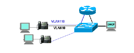
To allow the PC and telephone to be on the same Catalyst port, configure trunking with the new voice VLAN 110 as shown:
interface FastEthernet0/13
description phone and PC
switchport mode trunk
switchport trunk encapsulation dot1q
switchport voice vlan 110
switchport trunk native vlan 10
Repeat the configuration for all ports on the Catalyst where you have connected a telephone with a PC plugged into the telephone.
To allow the current DHCP server in data VLAN 10 to be used to assign IP addresses to the telephones, follow these steps:
-
Connect two router interfaces to two ports on the Cisco Catalyst 3524-XL, one in VLAN 10 and the other in VLAN 110.
-
On the router side, assign a valid address in each VLAN.
Note: With trunking configured, you can also achieve this with a single port connected from the Catalyst 3524-XL to the router.
-
Issue the ip helper-address command on the router interface that is connected to voice VLAN 110.
This allows DHCP broadcast packets received on the interface to be sent as unicast packets to the DHCP server in data VLAN 10.
The configuration on the router should be as shown:
router(config)#interface FastEthernet0/0
router(config-if)#ip address 10.10.10.19 255.255.255.0

router(config-if)#<description connected to catalyst port 0/10 data VLAN for PCs and DHCP server>

router(config)#interface FastEthernet0/1
router(config-if)#IP address 11.1.1.19 255.255.255.0
router(config-if)#IP helper-address 10.10.10.2
router(config-if)#<description connected to catalyst port 0/11 voice VLAN>
The configuration on the Cisco Catalyst 3524-XL should be:
router(config)interface FastEthernet0/10
router(config-if)#switchport access vlan 10
router(config-if)#<description port on data VLAN going to the router FE0/0>

router(config)interface FastEthernet0/11
router(config-if)#switchport access vlan 110
router(config-if)#<description port on voice VLAN going to the router FE0/1>
-
Configure the DHCP server with a new scope of addresses for the telephones (11.1.1.1.X) in voice VLAN 110.
If the DHCP server does not have a scope that matches the Relay Agent IP address, the DHCP request fails. You need to add the option 150 in that scope to provide the TFTP server address to the telephones. For step-by-step instructions on the configuration of the DHCP server for the telephones, refer to Configuring Windows 2000 DHCP Server for Cisco CallManager.
How the Solution Works
The DHCP server is able to provide addresses from the appropriate scope for both VLANs, based on the use of the Relay Agent field in the DHCP packets. A Relay Agent is the agent that is in charge of the conversion of the broadcast DHCP packets sent by the telephone into unicast packets that are sent to the DHCP server. This agent also converts the unicast DHCP packets sent from the DHCP server into broadcast packets that are sent on the telephone network. In this example, the Relay Agent is the VLAN 110 interface on the MSFC configured with the ip helper-address command.
When the DHCP server receives the DHCP discover message with a current IP address in the Relay Agent field, it uses that address to match the proper scope and assigns the IP address from it. You can see details of this protocol in RFC 3046 .
The DHCP packets that are exchanged in this example would be as shown:
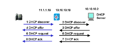
The blue lines show the DHCP packets that are sent to and from the IP telephone. These are the only packets that appear if the DHCP server is in the same Ethernet network as the telephones.
The black lines represent the DHCP unicast packets that the Relay Agent transmits to and from the DHCP server.
This table shows the details of the packets for this example. For details about the DHCP protocol and fields, refer to RFC 1541 .
| 1 DHCP Discover | 2 DHCP Discover |
|---|---|
IP Source Address = [0.0.0.0]
IP Destination Address = [255.255.255.255]

DHCP Client IP Address = [0.0.0.0]
DHCP Relay Agent = [0.0.0.0]
Client Hardware Address = 00070EEA5449
Message Type = 1 (DHCP Discover)
Parameter Request List:
...
    150= Unknown Option
...
|
IP Source Address = [11.1.1.19]
IP Destination Address =[10.10.10.2]

DHCP Client IP Address = [0.0.0.0]
DHCP Relay Agent = [11.1.1.19]
Client Hardware Address = 00070EEA5449
Message Type = 1 (DHCP Discover)
Parameter Request List:
...
    150= Unknown Option
...
|
| 4 DHCP Offer | 3 DHCP Offer |
IP Source Address = [10.10.10.2] IP Destination Address = [255.255.255.255] DHCP Client IP Address = [11.1.1.25] DHCP Relay Agent = [11.1.1.19] Client Hardware Address = 00070EEA5449 Message Type = 2 (DHCP Offer) .... Address Renewel Interval = 216000 (seconds) TFTF Server = "11.1.1.10" ... |
IP Source Address = [10.10.10.2] IP Destination Address = [11.1.1.19] DHCP Client IP Address = [11.1.1.25] DHCP Relay Agent = [11.1.1.19] Client Hardware Address = 00070EEA5449 Message Type = 2 (DHCP Offer) .... Address Renewel Interval = 216000 (seconds) TFTF Server = "11.1.1.10" ... |
| 5 DHCP Request | 6 DHCP Request |
IP Source Address = [0.0.0.0]
IP Destination Address = [255.255.255.255]

DHCP Client IP Address = [0.0.0.0]
DHCP Relay Agent = [0.0.0.0]
Client Hardware Address = 00070EEA5449
Message Type = 3 (DHCP Request)
Request Specific IP Address = [11.1.1.25]
Parameter Request List:
...
    150= Unknown Option
...
|
IP Source Address = [11.1.1.19]
IP Destination Address = [10.10.10.2]

DHCP Client IP Address =  [0.0.0.0]
DHCP Relay Agent = [11.1.1.19]
Client Hardware Address = 00070EEA5449
Message Type = 3 (DHCP Request)
Request Specific IP Address = [11.1.1.25]
Parameter Request List:
...
    150= Unknown Option
...
|
| 8 DHCP Ack | 7 DHCP Ack |
IP Source Address = [10.10.10.2] IP Destination Address = [255.255.255.255] DHCP Client IP Address = [11.1.1.25] DHCP Relay Agent = [11.1.1.19] Client Hardware Address = 00070EEA5449 Message Type = 5 (DHCP Ack) .... Address Renewel Interval = 216000 (seconds) TFTF Server = "11.1.1.10" ... |
IP Source Address = [10.10.10.2] IP Destination Address = [11.1.1.19] DHCP Client IP Address = [11.1.1.25] DHCP Relay Agent = [11.1.1.19] Client Hardware Address = 00070EEA5449 Message Type = 5 (DHCP Ack) .... Address Renewel Interval = 216000 (seconds) TFTF Server = "11.1.1.10" ... |
Related Information
Network segmentation is a great way to compartmentalize the various networks you need to run in your environment. This provides many benefits from both a management and security perspective. When segmenting your networks, one of the things that you have to consider and take care of is IP addressing. Dynamic Host Configuration Protocol (DHCP) is an age-old standard that has been used in the enterprise for handing out IP addresses to clients on the network. DHCP requires its own broadcast domain, which in turn requires VLANs. Many organizations are using Windows Server for DHCP on their networks. In this post, we will take a look at Windows Server DHCP VLAN configuration. These steps work for Windows Server 2012, 2016, 2019, and Windows Server 2022.wind
Why are VLANs needed for DHCP?
When a client is provisioned on a network segment and is set up to have IP addressing configured automatically using DHCP, the client makes broadcast queries on the network segment to notify the DHCP server configured that it needs an IP address. The DHCP server responds with the appropriate IP address for the network segment and the additional configuration for network connectivity on the segment.
VLANs (Virtual Local Area Networks) allow taking a physical network switch and logically segmenting the physical network environment into multiple network segments. This makes much more efficient use of network hardware since additional segments do not require additional physical network switches. By introducing VLANs, you can provision multiple network segments on the same switch.
When you spin up a new network segment IP address range, you want to pair this with a new VLAN or logical network segment. VLANs control broadcast ranges. Within each VLAN, clients can initiate the broadcast for a network IP address from a DHCP server. There are many different ways to have a Windows Server participate in a VLAN network segment. Before we look at the specifics related to DHCP VLAN configuration, let’s take a look at the multiple options for connecting the Windows host into a VLAN-backed network.
Connecting Windows Server to Multiple VLANs
There are many different ways to connect Windows Server to multiple VLANs. This includes the following:
- Additional network interfaces Untagged for VLAN traffic
- A single network interface with Tagged VLAN frames
- Routed Layer 3 connectivity to VLAN-backed subnets
Additional network interfaces Untagged for VLAN traffic
With VLANs, you hear two different terms tossed out there related to the VLAN you are working with – untagged, and tagged. When you talk about untagged frames, this means the Windows host is not tagging the Ethernet frames originating from the host with VLAN information. Instead, it is relying on the upstream switch it is plumbed into to handle that configuration.
So, essentially, the Windows Server is unaware of the VLAN and doesn’t care. It simply relies on its physical uplink to do any VLAN tagging for it to communicate appropriately. However, this means that if you want to have a Windows Server to be a part of multiple VLANs, it means you need a physical uplink for each separate VLAN, since it is relying on the switch to tag the traffic appropriately for a specific VLAN.
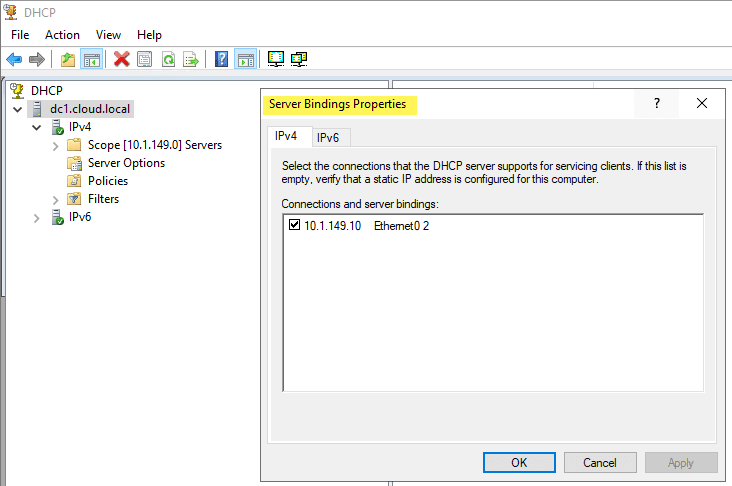
As shown below on a Windows Server 2019 server, you can specify the Bindings for the Windows DHCP Server so that it knows which interfaces to “listen” for DHCP on.
A single network interface with Tagged VLAN frames
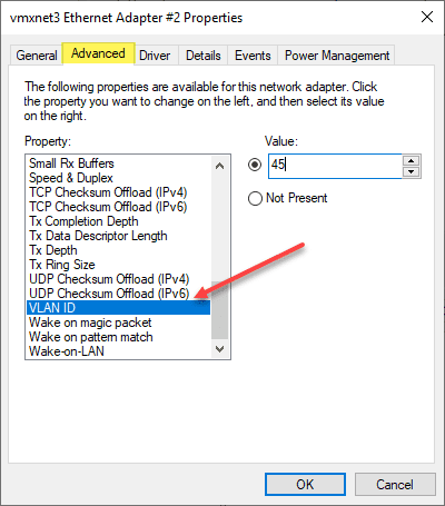
While there may be reasons that you use multiple physical uplinks with untagged frames for communicating with different VLANs, a more efficient approach is to use Tagged VLAN frames on a single network connection. When you use tagged frames, the Windows Server tags the frames appropriately for each VLAN it is associated with. The ability to Tag frames generally needs vendor-specific driver sets to be loaded, such as the Intel Pro Set drivers using Intel-based cards.
Routed Layer 3 connectivity to VLAN-backed subnets
The third option is simply relying on routing to take care of connectivity to the VLAN-backed subnets they need to communicate with. This technically does not connect the Windows Server into the VLAN as that would mean it would have the ability to be in the broadcast domain which is a Layer 2 VLAN construct. Instead, you are relying on Layer 3 connectivity to IP addresses. For many type of communication, including Windows Server 2012 DHCP VLAN configuration, this is all that is needed.
You can use all three of the methods above for Windows Server 2012, 2016, 2019, and Windows Server 2022 DHCP VLAN configuration. You can add multiple network adapters to each VLAN and have each scope listen on that specific network interface for DHCP requests. You can also use the tagging method listed above that allows adding multiple VLANs to a single network interface which allows keeping a single network adapter and connecting that physical network uplink to multiple VLANs.
You might assume the third option, since it is not connecting the uplink to the physical broadcast domain, would not be able to answer the broadcast DHCP request from the client on a specific VLAN. However, even though the DHCP server is not on the same broadcast domain/VLAN, there are really only two pieces of information the DHCP servers need to know to allocate an IP address on a particular subnet. This includes:
- Source subnet of the client
- MAC address of the client
You will note that the Windows Server DHCP server being a part of the VLAN is not a requirement for a successful DHCP request being made to the Windows Server. The third option is typically the option that I steer towards unless there are requirements for multiple physical uplinks for compliance or other security-based reasons. So, how does the Windows DHCP Server respond to a DHCP broadcast request if it is not on the same VLAN to take part in the broadcast traffic?
IP Helper Address, DHCP Relay, DHCP Proxy Address
This is made possible by the IP Helper Address which is sometimes referred to as DHCP Relay, or DHCP proxy address. Using an IP helper address, DHCP Relay, or DHCP proxy address allows the special DHCP broadcast messages to be forwarded from VLAN they originated from and forwarded to the DHCP server. This role is typically handled by a firewall or router device that is able to take the DHCP broadcast message and forward these to the DHCP server.
How does this work? When the DHCP client issues the DHCP broadcast request packet, is as of yet has no IP address configured. This being the case, it uses a broadcast with an all zero source address – 0.0.0.0. It also has no way to get to the DHCP Server with the lack of IP configuration. With this being the case, the client uses a general broadcast address of 255.255.255.255 as the destination with the DHCP request packet.
The device handling the DHCP proxy functionality receives the DHCP request packet from the client, replaces the destination address of 255.255.255.255 with the configured address of the server that was configured in the IP helper-address configuration. The client’s MAC address is included in the DHCP request so the receiving DHCP server knows the required MAC address of the client. This information is then forwarded to the DHCP server from the router, firewall, or another device in the role of the DHCP proxy.
The DHCP server issues an address now that it knows the subnet the client resides on along with the MAC address. It sends the DHCP response back to the DHCP Proxy device. The DHCP Proxy device then forwards the response to the correct MAC address of the requesting client and it is able to be configured with the IP address allowing network communication on the subnet.
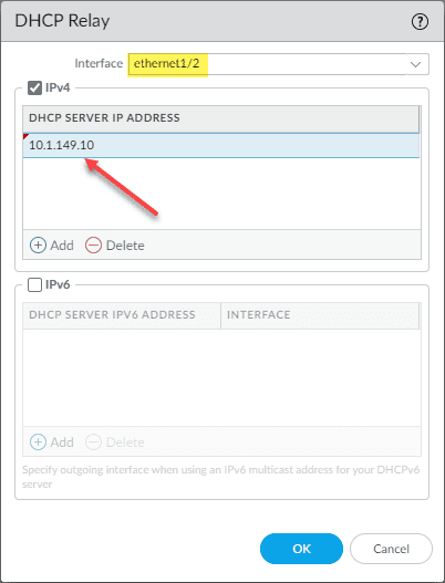
The configuration of DHCP Relay is generally simple but can vary depending on the vendor of router, firewall, or other device you might be using to perform this function. Below is the configuration of DHCP Relay on a Palo Alto firewall. You simply have to select the Interface and the DHCP Server IP Address you want to use for the target of DHCP requests.
Windows Server DHCP VLAN configuration for Virtual Machine DHCP servers
The principles still apply to Windows Server DHCP servers running inside a Windows Server virtual machine. The one method that is more difficult is the tagging of a single interface with multiple VLANs as this is not a feature that you can carry out with VMware Tools drivers that I am aware of. You can add multiple virtual NICs to a single VM and connect the virtual machine to different VLAN-backed port groups for each connection.
This will essentially place the Windows Server virtual machine on the same network segments as the clients that need addresses. Or, you can use the preferred method of using an IP Helper Address to forward the DHCP requests from all the other VLAN-backed subnets to the DHCP server and have the addresses issued by the server using only the single network connection.
Creating a Windows Server DHCP scope for a different VLAN
As detailed by the explanation above, the actual work of the Windows Server DHCP VLAN configuration takes place with the IP Helper Address/DHCP proxy device. Creating a Windows Server DHCP scope for a different VLAN is the same as creating a scope for the native VLAN network where the DHCP Server itself is located. Non-intuitively, you won’t see any part of the scope creation wizard that has you define the VLAN configuration. However, this is not needed in any of the configurations mentioned. With IP Helper Address, the packets are forwarded by the DHCP proxy to the DHCP server. If you are using different interfaces or tagged interfaces, the DHCP server will receive the DHCP broadcasts as normal.
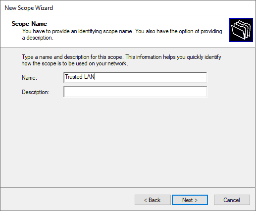
Set the name and description (optional) of the new DHCP scope.
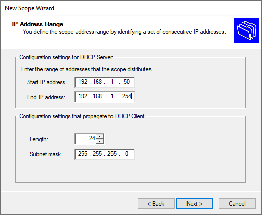
Specify the new DHCP address range.
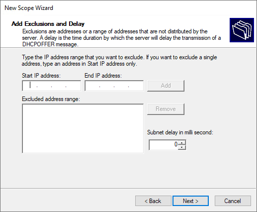
Set the exclusion range for the DHCP scope.
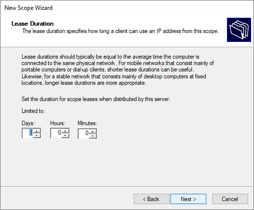
Specify the lease duration.
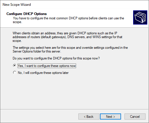
Configure the DHCP options for the new DHCP scope.
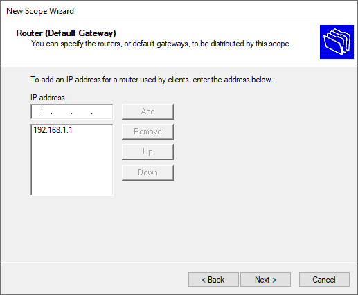
Define the default gateway of the new Windows Server DHCP VLAN configuration.
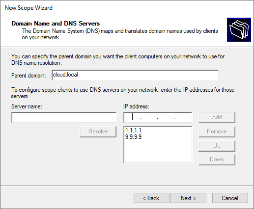
Configure domain name and DNS servers.
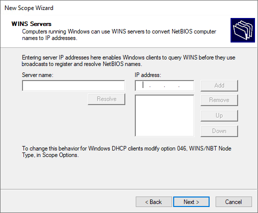
Setup any WINS server addresses.
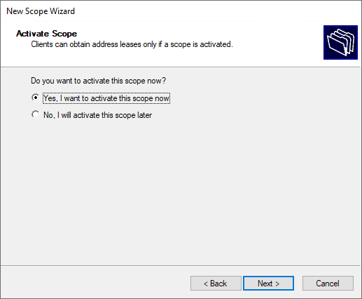
Activate the new DHCP scope.
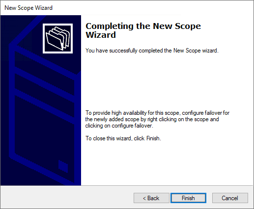
Complete the new DHCP scope wizard.
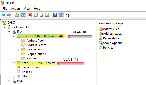
Below is an example of how my DHCP server looks after creating two different scopes for address leasing.
- 192.168.1.0/24 – associated with VLAN 10, which is not where the Windows Server DHCP server resides.
- 10.1.149.0/24 – associated with VLAN 149. This is the VLAN where the DHCP server resides.
Wrapping Up
Hopefully, this Windows Server DHCP VLAN Configuration: Detailed Guide will help any who may be trying to wrap their heads around the configuration of DHCP services for different VLANs and network segments in their network. By understanding the different means you have available to hand out IP addresses from a Windows DHCP Server you can effectively segment your network and easily handle IP addressing for all clients in the network, regardless of the VLAN they reside on.
Skip to content
To configure Yealink phones to get VLAN ID from the default DHCP Server follow the below instructions.
Step 1
Login to local windows dhcp server and configure a new scope option for Yealink phone.
a) Right click IPv4
b) select “Set Predefined Options”

Step 2
a) Click on “Add”
b) Fill the “Option Type”
c) Select “Data Type” as String.
d) Code is “132”
e) Finish the Options by clicking “OK” on all other dialog boxes.

Step 3
a) Right click Scope Options
b) Select “Configure Options”

Step 4
a) Scroll till the end of the list and select the Yealink VLAN option.
b) Under String value put the VLAN ID which you want to set on yealink phone.

In our daily life we learn lots of new things. As the time goes we forgets those and we may reach a situation where «Things You Probably Already Know, But Have Forgotten». I’m Shyju Kanaprath, the blogger of «Tech.. Logs..» and I blog here to avoid those kind of situations, at least for myself  . This blog keep me in track on such times..
View all posts by Shyju Kanaprath