
К сожалению, на сегодняшний день очень мало доступной и понятной литературы по модульным сеткам. И, честно говоря, почему так — непонятно, ведь данная информация очень полезна и важна для любого дизайнера.
Вся представленная информация на русском языке, касающаяся данной тематики или слишком обобщена, или годится, как некое пособие для ознакомления (и то только по теоретической части), но из всего этого непонятно, как можно применить её на практике.
Каждый, кто связан с дизайном, имеет представление о существовании модульных сеток и о том, что они важны, но как с ними работать и почему же, они так необходимы, является для многих вопросом.
ЧТО ЖЕ ТАКОЕ МОДУЛЬНАЯ СЕТКА?
Это некий шаблон или трафарет. Воображаемая сетка, образованная горизонтальными и вертикальными линиями, к которым «привязываются» основные элементы страницы (текстовое наполнение, иллюстрации и т.д.).
ОСНОВНОЙ ПРИНЦИП ПОСТРОЕНИЯ МОДУЛЬНОЙ СЕТКИ С ИСПОЛЬЗОВАНИЕМ ADOBE INDESIGN
1. Создаём новый документ.
a. Выбираем формат страницы А4 вертикальный (210×297 mm).
b. Поля (Margins) по умолчанию имеет заданный размер —12,7 mm, одинаковый по всем сторонам. Меняем все значения:
- Верх (Top) — 15 mm;
- Низ (Bottom) — 30 mm;
- Внутреннее поле (Inside) — 20 mm;
- Наружное поле (Outside) — 10 mm.
* ПРИВЕДЁННЫЕ ВЫШЕ РАЗМЕРЫ ПОЛЕЙ ЯВЛЯЮТСЯ РАСПРОСТРАНЕННЫМИ КЛАССИЧЕСКИМИ РАЗМЕРАМИ.
2. Устанавливаем единицы измерения — пункты (Points).
Edit > Preferences > Units & Increments
3. Строим сетку.
Для того, чтобы в итоге получилась интересующая нас сетка, изначально нам должны быть известны следующие данные:
- Общее количество строк, учитывая конструкцию сетки.
- Высота шрифта по выносимым элементам («EqПр»).
- Интервал между блоками, учитывая высоту шрифта и разрядку строк.
I. Создаём текстовой блок.
Указываем в нём интересующие нас параметры. В данном примере используется:
- Шрифт — MyriadPro;
- Кегль — 11 pt;
- Интерлиньяж (Leading) — 12 pt.
В итоге у нас должна быть следующая разбивка — 4 блока с расстояниями между ними.
* В ЗАВИСИМОСТИ ОТ ДИЗАЙНА ПРОЕКТА ДОЛЖНА БЫТЬ ПОДОБРАНА ГАРНИТУРА ОСНОВНОГО ТЕКСТА, ТАК КАК ИМЕННО ОТНОСИТЕЛЬНО ДАННОЙ ГАРНИТУРЫ БУДЕТ СТРОИТЬСЯ МОДУЛЬНАЯ СЕТКА.
II. Заполняем страницу «рыбным» текстом.
* ДЛЯ ТОГО, ЧТОБЫ ИСПОЛЬЗОВАЛОСЬ ВАШЕ ТЕКСТОВОЕ СОДЕРЖАНИЕ, НЕОБХОДИМО СОЗДАТЬ ТЕКСТОВОЙ ФАЙЛ В ПАПКЕ ADOBE INDESIGN CS4 С НАЗВАНИЕМ PLACEHOLDER.TXT.
III. Получаем информацию о количестве строк, которым мы располагаем.
- Кликнем по текстовому полю;
- Открываем вкладку Info.
* КОГДА ТЕКСТОВОЙ БЛОК ЯВЛЯЕТСЯ АКТИВНЫМ, ВСЯ ИНФОРМАЦИЯ О СОДЕРЖАНИИ ДАННОГО БЛОКА ОТОБРАЖАЕТСЯ ВО ВКЛАДКЕ INFO — КОЛИЧЕСТВО СИМВОЛОВ, СЛОВ, СТРОК И ПАРАГРАФОВ.
Количество строк (Lines) — это именно тот пункт, который интересует нас в первую очередь.
В данном примере у нас 56 строк.
Делим количество строк на количество блоков, то есть 56 / 4 = 14
14 — это количество строк.
Выбираем оптимально меньшее значение, так как нам понадобится ещё 3 строки.
13 × 4 + 3 = 55
Для построения сетки нам понадобится 55 строк. Следовательно, удаляем лишнюю.
Определяем высоту шрифта
Для того чтобы определить высоту шрифта:
- Создаём новый текстовой блок со следующим содержанием — «EqПр»;
- Используем ту же гарнитуру, что и в первом текстовом блоке, но со значением кегля 10 pt;
- Преобразовываем данный текст в кривые — Type > Create Outlines.
Н — высота текста — 8,719 pt.
Коэффициент для 8,719 pt равен — 0,8719 pt (так как кегль (размер шрифта) — 10 pt). Округляем — 0,872 pt.
Высоту нашего шрифта, то есть 11 pt умножаем на полученный коэффициент. Полученное число — 9,592 и есть высота нашего текста.
11 pt × 0,872 pt = 9,592 pt
На данный момент нам известна часть параметров, с помощью которых мы будем строить модульную сетку, а именно:
- Количество строк — 55;
- Высота текста — 9,592 pt (коэффициент — 0,872 pt);
- Интерлиньяж — 12 pt.
IV. Устанавливаем привязку Cap Height.
Object или правой клавишей мыши кликаем на текст > Text Frame Option > Baseline Options
Или данное окно можно также открыть при нажатии Ctrl + B
First Baseline > Offset – из выпадающего меню выбираем пункт Cap Height
4. Построение модульной сетки.
Переходим на Мастер-страницы (A-master).
A-master — это некий шаблон, который применяется ко всем создаваемым страницам, автоматически дублирующий все необходимые компоненты.
Именно здесь и будет создаваться наша модульная сетка.
Для перехода на A-master: Pages > A-master (двойной клик).
Дополнительные необходимые параметры для построения модульной сетки
55 (количество строк) — 1 (минус одна строка, так как она просчитывается по высоте (H)) = 54
54 (количество строк) × 12 pt (интерлиньяж) = 648 pt
Данное полученное значение является высотой от первой строчки до верхнего выносного элемента последней.
648 pt + 9,592 pt (высота текста) = 657,592 pt
Данное значение и есть высота нашего прямоугольника.
12 pt (интерлиньяж) × 2 − 9,592 pt (высота текста) = 14,408 pt
Интервал между блоками.
Сейчас мы имеем все необходимые параметры для того, чтобы можно было построить модульную сетку.
________________________________________
ШАГ 1
Рисуем прямоугольник с привязками по боковым полям. После чего вводим уже известную нам высоту прямоугольника, которая равняется 657,592 pt.
ШАГ 2
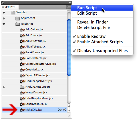
Открываем вкладку Scripts.
Windows > Automation > Scripts > MakeGrid
В открывшемся окне MakeGrid вводим следующие параметры:
- Ряды (Rows) — 4;
- Интервал между блоками (Row Gutter) — 14,408 pt.
ШАГ 3
Добавляем направляющие вокруг объектов.
Для этого выделяем 4 левых блока и открываем ещё один скрипт AddGuides.
Теперь выбираем следующие пункты:
- Верх (Тор);
- Низ (Bottom).
ШАГ 4
Выделяем 2 верхних блока, ещё раз открываем скрипт AddGuides и выбираем следующие пункты:
- Слева (Left);
- Справа (Right).
Далее удаляем имеющиеся у нас прямоугольники. Копируем слой с Guides и переносим на другую страницу, нижний — блокируем.
Ctrl + H — отображает или скрывает Guides.
ШАГ 5
Настройка базовых линий.
Alt + Ctrl + ’ — отображает или скрывает базовые линии.
Рисуем прямоугольник от верха документа до первого Guide. Смотрим, чему равняется высота прямоугольника.
Edit > Preferences > Grids
В графе Start указываем высоту прямоугольника.
Значение графы Increment Every должно совпадать со значением интерлиньяжа, то есть равняться 12 pt.
Перетаскивая фреймы в другое место, всегда будет соблюдаться кратность, учитывая, что интерлиньяж равен шагу базовых линий.
________________________________________
Продолжение статьи «Заполнение модульной сетки в Adobe InDesign»
As I was writing a feature article about grids for the next issue of InDesign Magazine, I started playing around with the MakeGrid script, which has been included with InDesign since at least CS3. I’ve used this script for years as a way to quickly divide a frame up into a grid of smaller frames. But did you know that you can use this script to create grids of circles, polygons, lines, or curves drawn in InDesign? (Warning: this is kind of fun, and can turn into a real time-sucker!) Here’s a simple example:
1. Draw a large diagonal line. This one is 4 inches long, 45 degree angle, 7 points thick.
2. Double-click on the MakeGrid script, found in the Samples folder in the Script panel. (The scripts panel is located in Window > Automation > Scripts in InDesign CS3/CS4, and Window > Utilities > Scripts in CS5).
3. Fill in the dialog as shown below, and click the OK button.
4. This should be the result:
5. Now, select the original diagonal line, flip it horizontally and run the script again:
6. Here is the result after applying the following stroke attributes, and changing the opacity to 40%:
The variations you could create on this are endless. What good is this? I’m not sure, but it is fun!
Bookmark
Please login to bookmark
Close
This article was last modified on December 20, 2021
This article was first published on July 15, 2010
Digitip 077 – Adobe InDesign, Gridded Images
Last Modification: 1-April-2009
The following tip looks at a few ways of working with image grids in InDesign.
Creating a Grid 101. To create a grid in which we can place images, start by drawing a rectangle frame about the size of the overall grid you’d like to create.
Next set your Frame Fitting Options (see previous post), with crop settings set to “0”
Creating the Grid
From Window > Automation, select Scripts. Olav Kvern has written some scripts that install with InDesign. In the Scripts panel, double click Application > Samples > JavaScript. The script we’re looking for is called “MakeGrid”.
We’re ready to run this script.
Oooh stop… You might find this such a cool script that you’d like to apply a shortcut to it, so you can use this as a command in the future without the need to navigate to the script in the scripts panel? (as is the case in my Scripts panel…). Easily done. Navigate to Edit > Keyboard shortcuts…, create a new Keyboards shortcut set if you’ve not done so yet previously, different to Default yet. (Click New Set.., then enter Name and choose based on option… normally that would be ‘Default’). Choose Product Area: Scripts and locate the script for which you’d like to add the shortcut. Enter the new shortcut, by pressing the preferred shortcut keys on the keyboard. Check the the shortcut you’ve chosen is unassigned (or else it will override other shortcuts in InDesign), then click Assign and OK…
Use the newly assigned shortcut or double click the script in the Script panel or select the script then choose Run Script from the panel menu to execute the script. A dialog appears asking you to enter the grid settings.
See as we’ve set Frame Fitting options for our graphic frame, we’ll opt to retain the Formatting and Contents, and as we won’t need the overall frame any more we’ll opt to remove that Original Object. Frame Type is Graphic. If you’re used to entering measurements in units other than points, you can enter those as well. E.g. enter .1 inch as “0.1in”, or enter 2 millimetres as “2mm”. Click OK to generate the Grid.
Note: this script has one nasty side effect: It changes the unit & measurement preferences in InDesign… These are easily reversed back to what you had before, right-click in the rulers and select your preferred preferences.
The Grid has now been created and we’re ready to select multiple images for insertion in the various frames.
Multiple images in individual frames
After placement we’ll look at a nice collection of images, beautifully aligned and distributed and set to our page with minimum effort.
One image in many frames
So what if you want one image in multiple frames? Well let’s go back to the point where we’d generated the Graphic Frames Grid… With the Selection Tool, select all of the Graphic Frames created earlier.
Next select Object > Paths > Make Compound Path
Notice the large ‘X” on the frame? The Compound path command is making the series of frames behave like “one”. This means we’re now ready to drop in that pic 🙂 to get to a different looking finished result.
Gridding it during placement (CS4)
There is another cool trick to add. We know that we can select multiple images right? and then place them on the page in InDesign? Using our cursor keys to toggle through the images?
But what about creating that grid right there and then?
Start by selecting multiple images for placement in the File > Place dialog (or use the Bridge as previously shown).
Press Command+Shift (Mac) or Ctrl+Shift (PC) and start click-dragging with the Loaded Placement Cursor.
Release the Cmd+Shift / Ctrl+Shift keys once you start dragging, but do not release the mouse-button.
Press the Left/Right Arrows in increase/decrease number of columns and press Top/Down Arrows to increase/decrease number of rows for the dynamic grid you’re drawing.
To Increase/Decrease the spacing between the columns and rows. Press the Shift Key whilst you’ve still got the mouse button held down and use the Left/Right Arrows to increase/decrease the space between columns and Top/Down Arrows to increase/decrease the space between the rows for the dynamic grid you are drawing.
Once you release the mouse button the selected images will be placed Left to Right, Top to Bottom with a Frame Fitting option set to “Fit Content Proportionally” and placement in Centre of frames.
One of the features that I like about InDesign is the ability to automate repetitive tasks using scripts. Since discovering this feature, using scripts have become part of my everyday work routine.
InDesign ships with 20 scripts, but with few exceptions the same scripts have been shipped with InDesign for the past six releases.
The scripts are (as described by Adobe itself on its website):
AddGuides.jsx – Adds guides around selected object/objects.
AddPoints.jsx – Adds points to the paths of the selected object or objects.
AdjustLayout.jsx – Moves objects by specified distances on right/left pages.
AlignToPage.jsx – Aligns objects to specified positions on a page.
AnimationEncyclopedia.jsx – Automatically creates buttons with different animation properties.
BreakFrame.jsx – Removes a selected text frame and its contents from a story.
CornerEffects.jsx – redraws the path of the selected item or items using a variety of corner effects. Corner effects can be applied to selected points on the path.
CreateCharacterStyles.jsx – Defines a complete character style based on the selected text.
CropMarks.jsx – Adds crop and/or registration marks around the selected object or objects.
ExportAllStories.jsx – Exports all stories in a document to a series of text files.
FindChangeByList.jsx – Performs a series of common text find/change operations by reading a tab-delimited text file.
ImageCatalog.jsx – Places all graphics in a specified folder in a “contact sheet” layout.
MakeGrid.jsx – Creates a grid by subdividing or duplicating the selected object or objects.
Neon.jsx – Applies a “blend” effect to the selected object or objects.
PathEffects.jsx – Changes the position of path points on the selected object or objects to add a creative effect.
PlaceMultipagePDF.jsx – Places all pages of a PDF.
SelectObjects.jsx – Selects objects on the active spread by their object type.
SortParagraphs.jsx – Sorts the paragraphs in the selection alphabetically.
SplitStory.jsx – Splits the text frames in the selected story into separate, unlinked text frames.
TabUtilities.jsx – Applies tab stops and indents to the selected text.
But after six releases, some of these scripts have either become redundant or improved upon elsewhere.
Scripts that have become redundant thanks to the user interface are:
- AlignToPage.jsx; and
- CornerEffects.jsx
Both scripts perform tasks which are just as easy to do in the actual user interface. Since InDesign introduced Live Corners, the CornerEffects script is actually more of a burden to use given that the script interface is hard to understand.

Also, objects made using the CornerEffects script do not hold their rounded corners once scaled.

Scripts that ship with InDesign but have been improved by other users:
- AdjustLayout.jsx;
- FindChangeByList.jsx; and
- MakeGrid.jsx
As each version of InDesign had different ways of interpreting javascript, the AdjustLayout behaved differently from version to version. Fed up with this, a co-author of Real World InDesign CS6 Ole Kvern has fixed this script and it can be downloaded here
For users working in millimetres, the MakeGrid script had one quibble that was it would always display measurements in points, but again the script has been fixed by Gerard Singelmann and can be downloaded here (this contains several scripts in German, the MakeGrid script is the one called Rahmen zerschneiden.jsx).
The FindChangeByList script itself hasn’t been improved upon, but the way of entering the find/replace values into the text file where the script gets its values from has. Kasyan Servetsky has a script called Recordfindchange which works by entering the values into the find/replace dialog box, then running the script which creates a text file which can be copied and entered into the text file being referenced by the FindChangeByList.jsx script. Kasyan’s script can be downloaded here.

Scripts that have been made obsolete by scripts made by others:
- CropMarks.jsx
- ExportAllStories.jsx
- PlaceMultipagePDF.jsx
- SortParagraphs.jsx
- SplitStory.jsx
The CropMarks Script had issues given that by default, it did not account for bleed and would put crop-marks within the gutters. An alternative by Loïc Teixeira resolves these two issues and can be downloaded here.

The ExportAllStories script still works but Kris Coppieters of Rorohiko has made a much better export. This one is a paid feature but if text exporting from InDesign is to be done often, is well worth it and can be downloaded here.
The PlaceMultipagePDF has been made quite obsolete by a much better script by Scott Zanelli called MultiPageImporter.jsx which not only imports PDFs but also allows page rotation, scaling, offsets, reverse page order… it’s massive! This script is one which is so good it even has its own manual. More information on the script can be downloaded here.

SortParagraphs again is a good script but Peter Kahrel has made a much better version.
SplitStory again works well but there is just a better version out there by Adi Ravid called StorySplitter which rather than just splitting the stories also has a dialog box with a few options. Again, that script can be found here.
If there any of the default scripts which have been made obsolete that I haven’t covered in this article, please let me know.
I use standard script MakeGrid.jsx (InDesign), make Grid boxes.
Hoe can I change fontsize, fonttype, textcolor etc. for text in those boxes?
I tried several ways (blue text eg.), but nothing changes the text… Text comes in boxes, thats OK, but I can’t change its font etc.
default code (at line 131 …):
if(myRetainFormatting == true){
myNewObject = myObject.duplicate();
myNewObject.geometricBounds = [myY1, myX1, myY2, myX2];
}
replaced code (at line131 …):
if(myRetainFormatting == true){
myNewObject = myObject.duplicate();
myNewObject.geometricBounds = [myY1, myX1, myY2, myX2];
tmp = myNewObject.textFrames.add(
{
geometricBounds :[myY1, myX1, myY2, myX2],
strokeWidth : 0,
size:30,
fillColor : «None»,
contents : «some text»
});
}