
Как известно, компьютеры были изобретены в 1871 году, но только в 1961 году контроль доступа к ним (ПК) начали осуществлять с помощью пароля. В настоящее время кроме буквенно-цифровых паролей доступно и множество новых, появившихся сравнительно недавно, способов идентификации: с помощью жестов, отпечатка пальца, распознавания лица и многое другое.
")
В этой статье мы рассмотрим как разблокировать компьютер, работающий на операционной системе Windows, с помощью платы Arduino и меток RFID (Radio Frequency Identification — радиочастотная идентификация). К компьютеру будут подключены плата Arduino и считыватель RFID меток и чтобы разблокировать компьютер нужно будет всего лишь поднести «правильную» радиочастотную метку к считывателю RFID меток.
На нашем сайте вы можете посмотреть все проекты, в которых используется радиочастотная идентификация.
Необходимые компоненты
- Плата Arduino Uno (купить на AliExpress).
- RC522 RFID reader (считыватель радиочастотных меток) (купить на AliExpress).
- RFID метки.
- USB кабель.
- Соединительные провода.
Реклама: ООО «АЛИБАБА.КОМ (РУ)» ИНН: 7703380158
Считыватель RFID меток RC522
Сейчас на рынке доступно достаточно много моделей считывателей RFID меток, однако для нашего проекта мы выбрали модуль RC522, работающий по интерфейсу SPI. Это достаточно дешевое устройство, доступное для покупки практически во всех магазинах радиоэлектроники. Модуль RC522 имеет интерфейсы SPI, UART и I2C, однако по умолчанию он использует интерфейс SPI. Внешний вид данного модуля показан на следующем рисунке.

В этом проекте модуль RC522 подключен к плате Arduino, а плата Arduino подключена к компьютеру. Когда RFID метку подносят к модулю RC522, плата Arduino с его помощью считывает идентификатор RFID метки (ID number) и передает его в компьютер.
Схема проекта
Схема подключения считывателя RFID меток RC522 к плате Arduino представлена на следующем рисунке.

Поскольку RFID модуль RC522 работает по интерфейсу SPI, то подключить его к плате Arduino достаточно просто – мы соединили его контакты MISO, MOSI, SCK и NSS к контактам SPI платы Arduino Uno. Модуль RC522 запитывается от контакта 5V платы Arduino. Сама же плата Arduino получает питание по USB кабелю от компьютера. Полный список соединений в схеме представлен в следующей таблице.
| Модуль RC522 | Плата Arduino Uno |
| VCC | 3.3V |
| GND | GND |
| RST | D9 |
| MISO | D12 |
| MOSI | D11 |
| SCK | D13 |
| SDA/NSS | D10 |
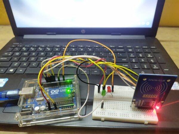
Внешний вид собранной конструкции проекта показан на следующем рисунке.

После сборки схемы проекта подключите плату Arduino к компьютеру. Определите COM порт компьютера, к которому подключилась плата Arduino – это можно сделать либо с помощью диспетчера устройств Windows, либо с помощью Arduino IDE как показано на следующем рисунке. В нашем случае плата Arduino оказалась подключенной к COM порту под номером 1.

После этого в плату Arduino необходимо загрузить код программы для работы с модулем RC522 – он приведен в конце статьи. После загрузки кода программы в плату откройте окно монитора последовательной связи (serial monitor). Затем прислоните RFID метку к модулю RC522, после чего вы увидите в окне монитора последовательной связи 5 значений. Эти значения необходимо скопировать себе в «укромное место» и закрыть окно монитора последовательной связи. Полученные нами значения показаны на следующем рисунке.

После этого скачайте каталог с настройками RFID (rfid_configuration folder) по следующей ссылке — rfid_configuration ZIP file. По этой ссылке вы скачаете ZIP архив, в котором будет 4 файла.
После распаковки ZIP архива зайдите в нем в каталог с именем 32 bit или 64-bit в зависимости от того 32 или 64-разрядная у вас операционная система. В этом каталоге откройте текстовый файл RFIDcredentials.txt. Вставьте в него свои значения из окна монитора последовательной связи (которые вы получили ранее) и обновите (укажите свои) имя пользователя (user name) и пароль (password). Если вы хотите добавить две карты для входа в операционную систему, то заполните и вторую строчку в файле RFIDcredentials.txt как показано на следующем рисунке.

После этого сохраните и закройте этот файл. Затем откройте из этой же папки файл RFIDCredSettings, измените в нем номер COM порта, к которому подключена плата Arduino, на свой, сохраните и закройте этот файл. Остальные значения в файле не меняйте.
Теперь скопируйте все 4 элемента нашего каталога, которые вы извлекли из скачанного ZIP архива и изменили в них часть значений на свои, в каталог C:\Windows\System32. Если система потребует подтверждения этой операции – подтвердите ее.

Теперь запустите файл реестра (register file) чтобы внести изменения в реестр. При этом, скорее всего, вы на своем экране увидите примерно следующее диалоговое окно:

Нажмите «yes», затем «ok». После этого осуществите выход из системы и вы увидите что в систему был добавлен еще один пользователь – с именем RFID.

Вход в учетную запись этого пользователя теперь можно будет осуществлять с помощью RFID карт/меток. То есть никакого пароля на вход в систему вводить уже не будет нужно – достаточно будет всего лишь прислонить RFID метку к RFID считывателю и вход в систему произойдет автоматически.
Объяснение программы для Arduino
Полный код программы приведен в конце статьи, здесь же мы кратко рассмотрим его основные фрагменты.
Первым делом в программе нам необходимо подключить заголовочные файлы всех используемых библиотек и определить контакты для RFID RST_PIN и SS_PIN. Если в вашей Arduino IDE еще нет библиотеки для работы с модулем RC522 (mfrc522 library), то вы можете скачать ее по следующей ссылке — MFRC522 Arduino Library. После скачивания библиотеку необходимо добавить в вашу Arduino IDE.
|
#include <SPI.h> #include <MFRC522.h> #define RST_PIN 9 #define SS_PIN 10 MFRC522 mfrc522(SS_PIN, RST_PIN); MFRC522: : MIFARE_KEY; |
Затем в функции void setup мы инициализируем последовательную связь со скоростью 9600 бод и связь по интерфейсу SPI со считывателем RFID меток.
|
void setup() { serial.begin(9600); while(!Serial); SPI.begin(); mfrc522.PCD_Init(); for(byte i = 0; i < 6; i++) Key.KeyByte[i] = 0xFF; serial.print(‘>’); } |
После этого в функции void loop() мы будем ждать когда к считывателю прислонят RFID карту.
|
void loop() { if( ! mfrc522.PICC_IsNewCardPresent() ) return; if( ! mfrc522.PICC_ReadCardSerial() ) return; send_tag_val (mfrc522.uid.uidByte, mfrc522.uid.size); delay(1000); } |
Если карта будет найдена, то произойдет вызов функции send_tag_val, которая передаст данные из RFID метки в компьютер с помощью порта последовательной связи. Эти данные в компьютере будут сравниваться с данными, которые мы ранее сохранили в файле – при их совпадении будет осуществлен вход (разблокировка) в систему.
|
void send_tag_val (byte *buffer, byte buffersize) { serial.print(«ID»); for (byte i = 0; i < buffersize; i++) { serial.print(buffer[i], DEC); serial.print(» «); } serial.printIn(0, DEC); serial.print(‘>’); } |
Более подробно работа проекта показана в видео, приведенном в конце статьи.
Исходный код программы (скетча)
|
1 2 3 4 5 6 7 8 9 10 11 12 13 14 15 16 17 18 19 20 21 22 23 24 25 26 27 28 29 30 31 32 33 34 35 36 37 38 39 40 41 |
#include <SPI.h> #include <MFRC522.h> #define RST_PIN 9 #define SS_PIN 10 MFRC522 mfrc522(SS_PIN, RST_PIN); MFRC522::MIFARE_Key key; void setup() { Serial.begin(9600); while (!Serial); SPI.begin(); mfrc522.PCD_Init(); for (byte i = 0; i < 6; i++) key.keyByte[i] = 0xFF; Serial.print(‘>’); } void loop() { if ( ! mfrc522.PICC_IsNewCardPresent()) return; if ( ! mfrc522.PICC_ReadCardSerial()) return; send_tag_val(mfrc522.uid.uidByte, mfrc522.uid.size); delay(1000); } void send_tag_val(byte *buffer, byte bufferSize) { Serial.print(«ID:»); for (byte i = 0; i < bufferSize; i++) { Serial.print(buffer[i], DEC); Serial.print(» «); } Serial.println(0, DEC); Serial.print(‘>’); } |
Видео, демонстрирующее работу проекта
Загрузка…
4 567 просмотров

Для реализации данного примера нам понадобится:
Arduino nano: http://ali.pub/1x1jri
Контактные провода : http://ali.pub/1th4xf
Rc522: http://ali.pub/26gq1k
Buzzer: http://ali.pub/1hzdau
Прежде чем приступить к материалу, я Вас попрошу, если нравится то, что я делаю и хотите следить за моей деятельностью, то рекомендую подписаться на мой телеграмм канал: https://t.me/ypavla
Там я публикую новости о вышедших видео, статьях и разные устройства для умного дома и не только показываю.
Спасибо за внимание, теперь продолжим.
Для начала давайте разберемся что за модуль RC522. Это модуль считывания авторизационных карт (пропусков) Данный модуль можно использовать в Системах контроля доступом, собственно для этого мы его и используем.
Характеристики (от продавца):
— Напряжение: 3.3В
— Потребляемый ток в активном состоянии:13-26 мА
— Потребляемый ток в состоянии ожидания: 10-13 мА
— Ток в режиме сна: менее 80 мкА
— Пиковое потребление: менее 30 мА
— Рабочая частота: 13.56 МГц
— Поддержвиаемые типы карт: MIFARE S50, MIFARE S70, MIFARE UltraLight, MIFARE Pro, MIFARE DESfire
— Интерфейс: SPI
— Размеры: 40х60 мм
Данный модуль подключается по шине SPI. Для подключения требуется 7 проводов.
Ну вроде бы все, с модулем разобрались. Давайте теперь перейдем к нашему проекту.
Проект работает таким образом:
Для начала подключим все по схеме приведенной ниже.

Buzzer здесь используется не активный, но можно использовать и трех пиновый, просто больше проводов займет.
Далее загружаем готовый скетч который приведен ниже, и считываем с помощью RC522 карту, которую будем использовать для авторизации.
/**
* ----------------------------------------------------------------------------
* This is a MFRC522 library example; see https://github.com/miguelbalboa/rfid
* for further details and other examples.
*
* NOTE: The library file MFRC522.h has a lot of useful info. Please read it.
*
* Released into the public domain.
* ----------------------------------------------------------------------------
* This sample shows how to read and write data blocks on a MIFARE Classic PICC
* (= card/tag).
*
* BEWARE: Data will be written to the PICC, in sector #1 (blocks #4 to #7).
*
*
* Typical pin layout used:
* -----------------------------------------------------------------------------------------
* MFRC522 Arduino Arduino Arduino Arduino Arduino
* Reader/PCD Uno/101 Mega Nano v3 Leonardo/Micro Pro Micro
* Signal Pin Pin Pin Pin Pin Pin
* -----------------------------------------------------------------------------------------
* RST/Reset RST 9 5 D9 RESET/ICSP-5 RST
* SPI SS 1 SDA(SS) ** custom, take a unused pin, only HIGH/LOW required **
* SPI SS 2 SDA(SS) ** custom, take a unused pin, only HIGH/LOW required **
* SPI MOSI MOSI 11 / ICSP-4 51 D11 ICSP-4 16
* SPI MISO MISO 12 / ICSP-1 50 D12 ICSP-1 14
* SPI SCK SCK 13 / ICSP-3 52 D13 ICSP-3 15
*
*/
#include &lt;SPI.h&gt;
#include &lt;MFRC522.h&gt;
#define RST_PIN 9 // Configurable, see typical pin layout above
#define SS_1_PIN 10 // Configurable, take a unused pin, only HIGH/LOW required, must be diffrent to SS 2
#define SS_2_PIN 8 // Configurable, take a unused pin, only HIGH/LOW required, must be diffrent to SS 1
#define OUT_PIN_GREEN 4 // green LED - card OK
#define OUT_PIN_RED 5 // red LED - another card
#define NR_OF_READERS 2
#define BUZZER 3 // buzzer
byte ssPins[] = {SS_1_PIN, SS_2_PIN};
MFRC522 mfrc522[NR_OF_READERS]; // Create MFRC522 instance.
/**
* Initialize.
*/
void setup() {
Serial.begin(9600); // Initialize serial communications with the PC
while (!Serial); // Do nothing if no serial port is opened (added for Arduinos based on ATMEGA32U4)
pinMode (OUT_PIN_GREEN, OUTPUT);
pinMode (OUT_PIN_RED, OUTPUT);
pinMode(BUZZER, OUTPUT);
noTone(BUZZER);
SPI.begin(); // Init SPI bus
for (uint8_t reader = 0; reader &lt; NR_OF_READERS; reader++) {
mfrc522[reader].PCD_Init(ssPins[reader], RST_PIN); // Init each MFRC522 card
}
}
/**
* Main loop.
*/
void loop() {
uint32_t id;
for (uint8_t reader = 0; reader &lt; NR_OF_READERS; reader++) { // Look for new cards if (mfrc522[reader].PICC_IsNewCardPresent() &amp;&amp; mfrc522[reader].PICC_ReadCardSerial()) { Serial.print(F("&gt;ID:"));
dump_byte_array(mfrc522[reader].uid.uidByte, mfrc522[reader].uid.size);
Serial.println();
//Serial.print(F("PICC type: "));
MFRC522::PICC_Type piccType = mfrc522[reader].PICC_GetType(mfrc522[reader].uid.sak);
/// Serial.println(mfrc522[reader].PICC_GetTypeName(piccType));
Serial. println (id);
// LED configure
byte uidCard[4] = {0xA6, 0x4B, 0xC4, 0x3B};
for (byte i = 0; i &lt; 4; i++) {
if (uidCard[i] == mfrc522[reader].uid.uidByte[i]) {
digitalWrite (OUT_PIN_GREEN, HIGH);
tone(BUZZER, 2000); // 2KHz sound signal...
delay (400);
noTone(BUZZER); // Stop sound...
digitalWrite (OUT_PIN_GREEN, LOW);
return;
}
else
{
digitalWrite (OUT_PIN_RED, HIGH);
tone(BUZZER, 2000); // 2KHz sound signal...
delay (1500);
noTone(BUZZER); // Stop sound...
digitalWrite (OUT_PIN_RED, LOW);
return;
}
}
}
// Halt PICC
mfrc522[reader].PICC_HaltA();
// Stop encryption on PCD
mfrc522[reader].PCD_StopCrypto1();
} //if (mfrc522[reader].PICC_IsNewC
} //for(uint8_t reader
/**
* Helper routine to dump a byte array as hex values to Serial.
*/
void dump_byte_array(byte *buffer, byte bufferSize) {
for (byte i = 0; i &lt; bufferSize; i++) {
Serial.print(buffer[i] &lt; 0x10 ? " 0" : " ");
Serial.print(buffer[i], HEX);
}
}
В этом скетче нас интересует для изменения только одна строчка:
byte uidCard[4] = {0xA6, 0x4B, 0xC4, 0x3B};
Здесь Нужно прописать свой id карточки, которую можно будет отсканировать этим же скетчем открыв монитор com порта.
id карты высветится в HEX формате. и нужно его записать по группам в этой строчке, при этом оставив в каждой группе “0x”.
После этих манипуляций. загрузим скетч в ардуино и перейдем уже к непосредственной настройке ПК.
Для настройки ПК скачаем Архив: https://yadi.sk/d/dP7POaM23RN7W3
И зайдем в папку RC522WindowsLogon > Setting-PC здесь выберем папку 32 или 64 в зависимости от рязрядности вашей ОС в моем случае 64.
В этой Папке находятся три файла один с расширением .dll и два .txt
Вот файлы с расширением .txt нам и нужно отредактировать.
Сначала откроем первый файл под названием RFIDCredentials.txt Там будет написана строчка ” A6 4B C4 3B|psenyukov|123″
Где ” id карты|логин|пароль” и Важно, что перед id карты стоит пробел, иначе у Вас логиниться не будет. Вообщем исправьте этот файл под свои нужды, а именно введите свой id логин и пароль.
В следующем файле “RFIDCredSettings.txt” нужно только указать правильный номер Com порта к которому у Вас будет подключена Ардуино. Важно понимать, что каждый ЮСБ имеет свой номер СОМ порта при подключенной к нему Ардуино, это нужно выйснить и вписать в Файл.
После всех манипуляций с редактированием файлов, нужно эти три файла .dll и два .txt перенести в C:\Windows\System32
После этого в Папке “RC522WindowsLogon > Setting-PC” есть файлик “Register.reg” его нужно запустить и согласиться со всеми полями предупреждения которые выскочат в последствии.
После этого перезагружаем ПК и у Нас появится еще одна учетная завись “rfid” и мы теперь приложив карточку можем залогинится без ввода пароля.
Ну а для тех кто не внимательно читал и для Визуальной демонстрации Видео :
https://www.youtube.com/watch?v=TTfs9KfgqIc
As many of us know computers were invented around 1871, but it was not until 1961 we had them password protected. Early in the 19’s we used pins and alphanumeric characters as passwords for our computers, today we have many types of verification methods like Password, Pin, Pattern, Gesture, Fingerprint recognition, Face recognition and much more. But still, it is a pain for me to log in to my office computer every time I get back to it after a short break.
So, in this project, we are going to learn how to unlock windows laptops by using RFID tags. The Arduino Board and RFID reader will always be connected to the computer and to unlock system I only need to swap my RFID tag over RFID reader. With this Arduino RFID windows Login Project I can unlock system very fast and without typing any passwords, also later I am planning to use my office ID card as the RFID tag since my ID card already has an RFID tag in it and I can program the Arduino to verify it. Sounds interesting right, so let’s get started……
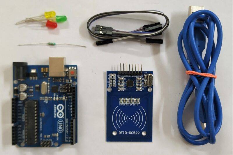
Materials Required:
- Arduino UNO (any Arduino can be used)
- RC522 RFID reader
- RFID tags
- Connecting wires
- USB cable
RC522 RFID Module:
There are many types of RFID readers available in the market but in this project, we have used RC522 SPI based RFID module. This is cheap and easily available at online shopping websites. This is RFID has SPI, UART and I2C interface but by default, it comes with SPI interface. The MFRC522 RFID Reader module is shown below.

We have already used RFID modules with Arduino previously to build other cool RFID projects like
- RFID Door Lock
- RFID Attendance system
- RFID Security system
- RFID Voting Machine
In this project, the RC522 RFID Module shown above is connected to Arduino and the Arduino itself is connected to the computer. When a RFID tag is placed near this reader, the Arduino reads the rfid tag ID number and sends it to computer.
Circuit Diagram:
The complete circuit diagram to interface RFID RC522 with Arduino is given below.

As you can see the connections are pretty simple. Since the RFID module works with SPI communication we have connected the MISO,MOSI,SCK and NSS pin to the SPI pins of the Arduino Uno board. The RFID module is powered by the 5V pin of the Arduino. The Arduino UNO itself will be always connected to Laptop and hence we can get it powered by the laptop USB port. The connection details are listed in table below.
| RFID RC522 | ARDUINO |
| VCC | 3.3V |
| GND | GND |
| RST | D9 |
| MISO | D12 |
| MOSI | D11 |
| SCK | D13 |
| SDA/NSS | D10 |

Setting up the RFID Unlock System:
After the circuit is built, as shown above, connect the USB cable between Arduino and the system (laptop or PC). Now the user needs to find the com port for Arduino. To find com port you can either use device manager or you can find it in Arduino IDE as shown below. My COM port number here is 1; yours might be different make a note of this COM port number as it will be used later.

Now the user needs to upload the RC522 Arduino code to your Arduino module. The complete code is given at the bottom of this page; the explanation of the code will also be discussed later in this article. After the code is uploaded open the serial monitor. Then place the RFID tag over RFID reader and you will see the 5 values on the serial monitor. The user needs to copy it and close the serial monitor. My values are shown in the serial monitor snapshot below.

Download the rfid_configuration folder from the given link below. The link will download a ZIP file with four items in it.
Download rfid_configuration ZIP file
After extracting the ZIP file get into the folder named 32 bit or 64-bit folder (according to your operating system) and open the notepad named RFIDcredentials.txt. Paste the RFID values and update the system user name and password. If you want to add two cards then add the same credential in the second row as shown below.

Then save and close this file. Now come back and open the RFIDCredSettings notepad and update the Arduino port in it then save and close. Again my COM port number is 1, update it with your COM port number. Leave the rest to default values as shown below.
Now copy all four items and paste them in C:\Windows\System32. If it asks for any permission just give or click on yes. Now run register file to register the changes.

When you run the Register file you might get the following dialog box.

Press yes then ok. Now lock the system and the user will see another user option available with your current user.

Now the user can unlock the system by using RFID card. Meaning, now we do not need to input the password, just place RFID tag over RFID reader and windows will be unlocked immediately.
RFID Arduino Code:
The coding part of this project is easy and simple; the explanation of the same is given. First of all, we need to include header files and define pins for RFID RST_PIN and SS_PIN. If you do not have the mfrc522 library installed already you can download and add it from the following link.
MFRC522 Arduino Library
#include <SPI.h> #include <MFRC522.h> #define RST_PIN 9 #define SS_PIN 10 MFRC522 mfrc522(SS_PIN, RST_PIN); MFRC522: : MIFARE_KEY;
Then in the void setup, we have initialized the serial and SPI communication and RFID reader
void setup()
{
serial.begin(9600);
while(!Serial);
SPI.begin();
mfrc522.PCD_Init();
for(byte i = 0; i < 6; i++)
Key.KeyByte[i] = 0xFF;
serial.print('>');
}
Now in loop function, we are waiting for the card.
void loop()
{
if( ! mfrc522.PICC_IsNewCardPresent() )
   return;
if( ! mfrc522.PICC_ReadCardSerial() )
   return;
send_tag_val (mfrc522.uid.uidByte, mfrc522.uid.size);
delay(1000);
}
If the card found send_tag_val called an RFID tag data will be transferred to the system using serial print. This serial print value will be compared with the file that we placed earlier and if it a match the windows will unlock itself.
void send_tag_val (byte *buffer, byte buffersize)
{
   serial.print("ID");
   for (byte i = 0; i < buffersize; i++)
{
   serial.print(buffer[i], DEC);
   serial.print(" ");
}
   serial.printIn(0, DEC);
    serial.print('>');
}
The complete working of the project is shown in the video given below. Hope you understood the project and enjoyed building it. If you have any problems leave them in the comment section. Also, feel free to use the forums for other technical questions.
Introduction
Hey guys, welcome back to Techatronic.
HTML Image as link

Are you getting bored of entering the password again and again to unlock your PC? Well, we have a solution for this.
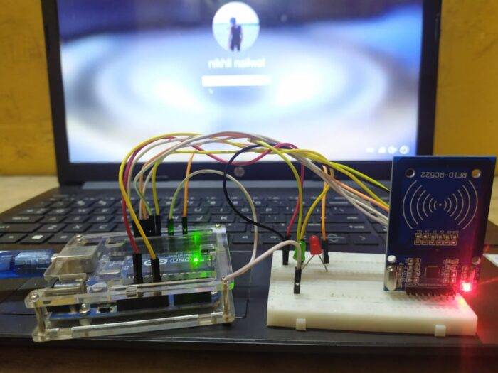
Let’s make a project in which you have to tap a smart card to the RFID reader module to unlock your PC. We are going to make windows login RFID project using Arduino UNO.
Apart from it,
you can also sign in to various applications. You just need to provide the id and password of the application to the Arduino.
You can also check out more mini projects and final year projects made by us. The basic working principle of this project is that we are using the Arduino as a keyboard and tapping the smart card automatically enters the password given by us.
The code and the circuit diagram for the project are given below.
How to Set up the Software for the Rfid project
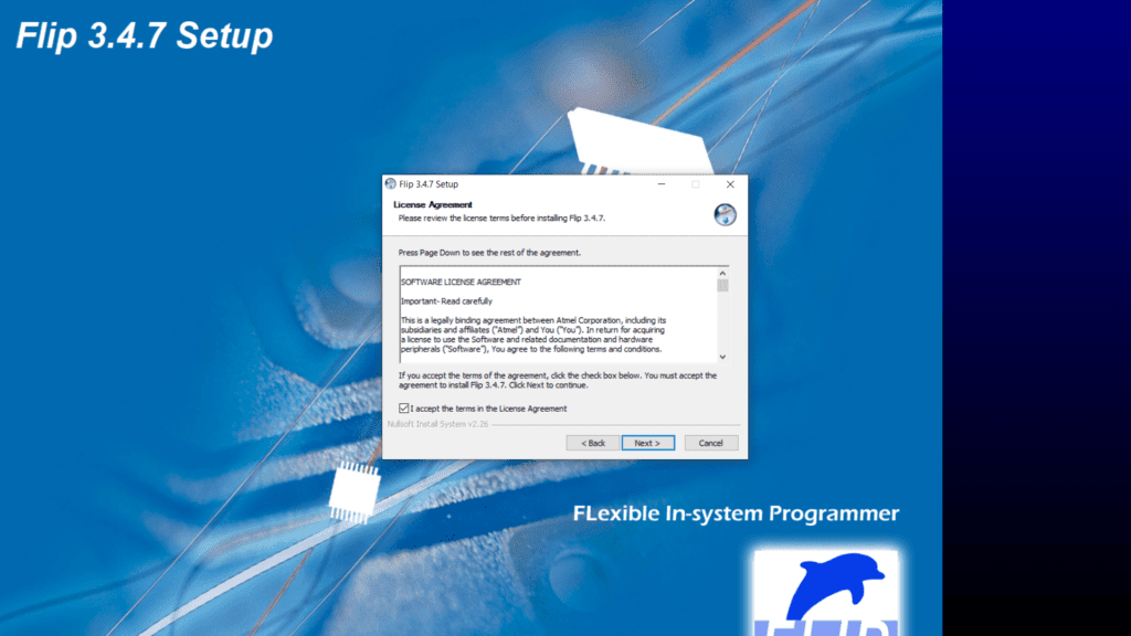
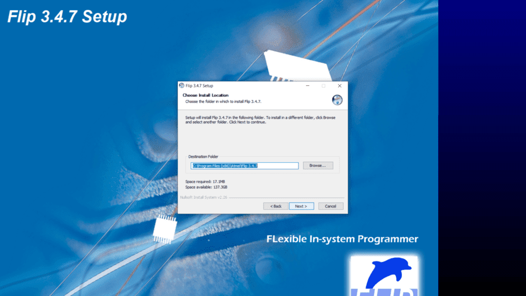
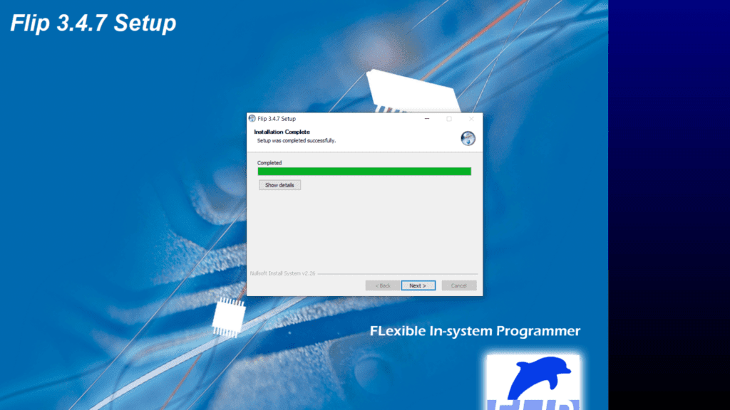
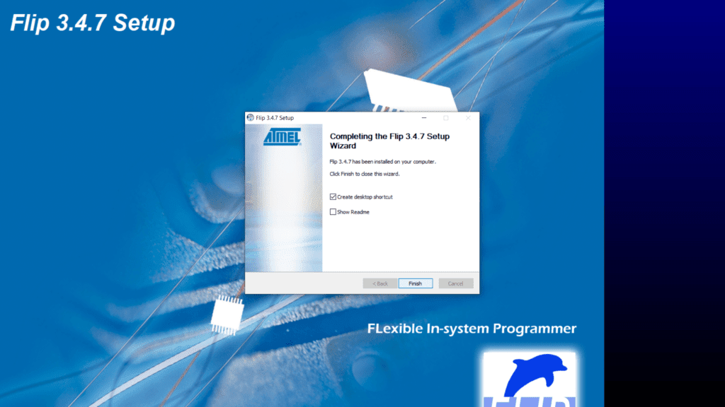
First of all, you have to download the flip software into your windows machine and then install it.
FlipInstaller-3.4.7.112.exe
Here are some screenshots, you can refer to them if you don’t know how to set up the flip software.
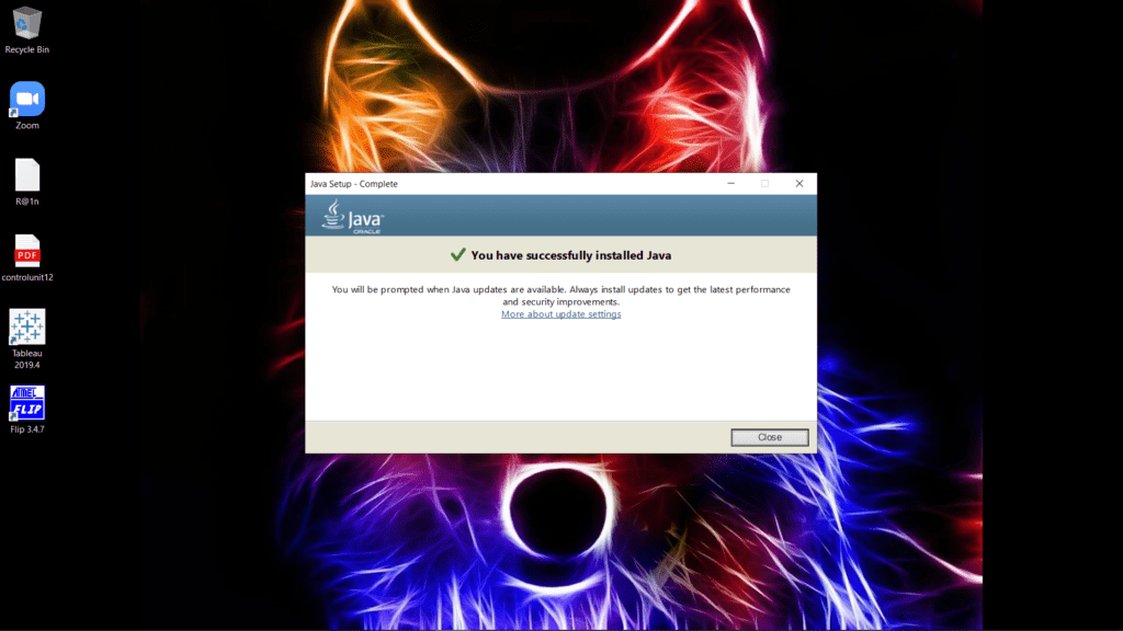
After it please install the java runtime set up so that the flip software can perform its task easily.
JavaSetup8u261
You can refer to the screenshots given below if you cannot install the java runtime setup.

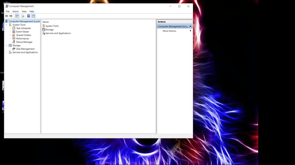
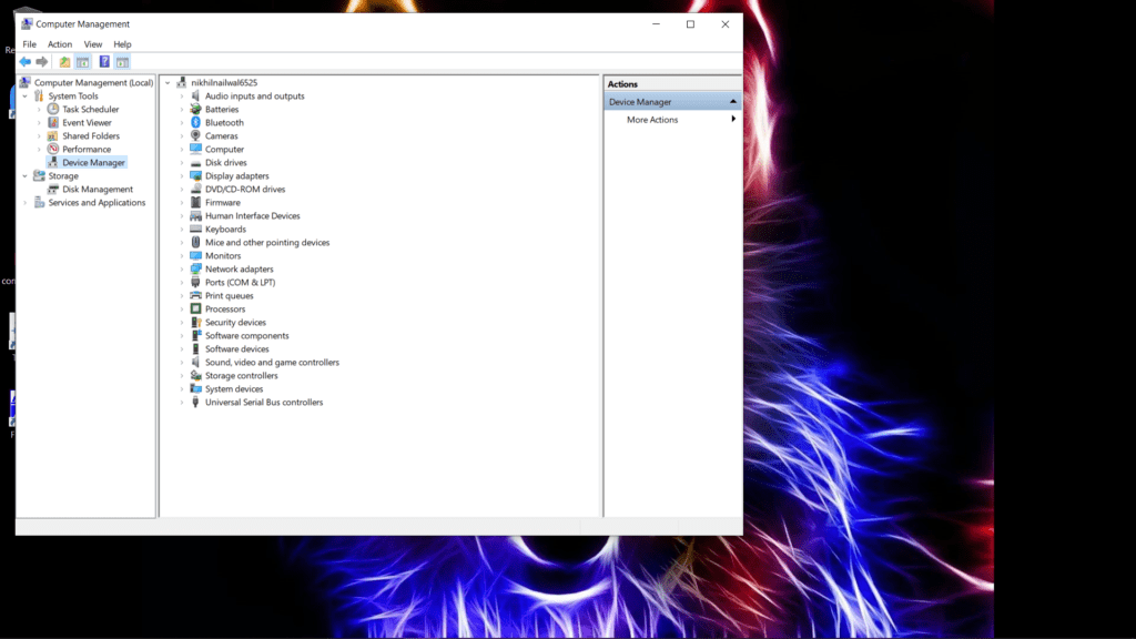
After the installation of both the software upload the given code to the Arduino and make the proper connections. Then open the computer management and open the device manager as shown below.
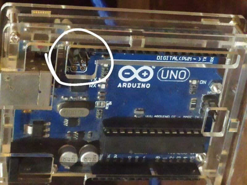
Touch the top two pins of Arduino with each other so that you can enter into DFU mode. Then you will see the Arduino board under USB devices in the device manager.
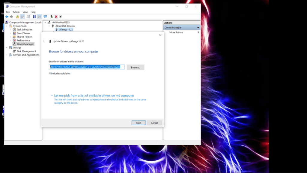
Click on it and select update driver. It will ask you for the path of the new driver then first of all download the given driver and select its path. After changing the driver successfully close this window and return to the home screen.
Download this file which is used for turning the Arduino into a keyboard (turnintokeyboard). This file will run in CMD (command window). After this eject your USB cable of the Arduino and plug it again. Now your system will identify the Arduino as a keyboard device. Just tap the card to the reader module and your system will unlock itself. If you tap the correct RFID tag then the green LED will go on and if the card id doesn’t match then the red LED will go on.
Windows Rfid Login
NOTE: If you don’t want to use the Arduino as a keyboard, run the bat file whose name is turning Arduino. Eject and plug in the USB again so that the Arduino will become a normal USB device.
Components Required
| Arduino UNO | BUY LINK |
| RC522 RFID module | BUY LINK |
| Jumper wires | BUY LINK |
| breadboard | BUY LINK |
| Red and green LEDs | BUY LINK |
| USB cable for uploading the code | BUY LINK |
Circuit Diagram for RFID project Windows Login

Connection Table
| Arduino UNO | RFID – RC522 Module | ||
| 10 Pin | SDA Pin | ||
| 13 Pin | SCK Pin | ||
| 11 Pin | MOSI Pin | ||
| 12 Pin | MISO Pin | ||
| NO Pin | ITQ Pin | ||
| GND | GND | ||
| RST Pin | RST Pin | ||
| 3.3 V Pin | 3.3 V | ||
| Arduino UNO | LED G | LED R | 220-ohm Resistor |
| 4 Pin | Anode Pin | ||
| 7 Pin | Anode Pin | ||
| GND | Terminal 1 | ||
| Cathode Pin | Cathode Pin | Terminal 2 |
Code for RFID Windows Login
NOTE: Please upload the code which is given below to the Arduino. You have to install <SPI.h> and <MFRC522.h> libraries into your IDE software. Check here to learn how to install a zip library to the Arduino IDE.
Modify the code by changing the password for your windows machine. Also, provide the key for the smart card that you are using. You can view the unique id for your smart card by using one of our articles on it.
 //Techatronic.com
 uint8_t buf[8] = { 0 };
 #include <SPI.h>
 #include <MFRC522.h> // RFID library
 #define SS_PIN 10 //RX slave select
 #define RST_PIN 9
 int gled = 7; // optional
 int rled = 4;// optional
 MFRC522 mfrc522(SS_PIN, RST_PIN); // Create MFRC522 instance.
 String card_ID=""; //
 String password="xxxxxxxxxxxxxx" ; // Change It To Your Windows / fb / any Account's Password
 String rfid="xxxxxxxxxxxxxx";// UID (unique Id Code Of Your Rfid Tag)
 void setup() {
  Serial.begin(9600); // Initialize serial communications with the PC
  SPI.begin(); // Init SPI bus
  mfrc522.PCD_Init(); // Init MFRC522 card
  pinMode(gled,OUTPUT);
  pinMode(rled,OUTPUT);
 }
 void loop() {
  //look for new card
   if ( ! mfrc522.PICC_IsNewCardPresent()) {
  return;
  }
  if ( ! mfrc522.PICC_ReadCardSerial()) {
  return;//if read card serial(0) returns 1, the uid struct contians the ID of the read card.
  }
  for (byte i = 0; i < mfrc522.uid.size; i++) {
   card_ID += mfrc522.uid.uidByte[i];
  }
  Serial.println(card_ID);
     if(card_ID==rfid){digitalWrite(gled,HIGH);
    typeLiteralString(password);
    pressKey("enter"); releaseKey("enter");
    digitalWrite(gled,LOW); delay(200);digitalWrite(gled,HIGH); delay(200);digitalWrite(gled,LOW);
    }
    if(card_ID!=password){
 digitalWrite(rled,HIGH);  digitalWrite(rled,LOW); delay(200);digitalWrite(rled,HIGH); delay(200);digitalWrite(rled,LOW); }   else{ goto cont;}
 delay(1000);
 cont:
 delay(1000);
 card_ID="";
 }
 boolean isModifier(int keycode) {
   boolean result = false;
   if (keycode >= 224 && keycode <= 231) { // if the keycode is a modifier key
     result = true;
   }
   return result;
 }
 void pressModifier(String keyname) {
   pressModifier(getKeycode(keyname));
 }
 void pressModifier(int keycode) {
   int modifiermask = 0;
   if (isModifier(keycode)) { // if the keycode represents a modifier key
     modifiermask = getModifierMask(keycode);
     buf[0] = buf[0] | modifiermask;
     Serial.write(buf, 8); // Send key report
   }
 }
 void releaseModifier(String keyname) {
   releaseModifier(getKeycode(keyname));
 }
 void releaseModifier(int keycode) {
   int modifiermask = 0;
   if (isModifier(keycode)) { // if the keycode represents a modifier key
     modifiermask = getModifierMask(keycode);
     buf[0] = buf[0] & (~modifiermask);
     Serial.write(buf, 8); // Send key report
   }
 }
 void releaseAllModifiers() {
   buf[0] = B00000000;
   Serial.write(buf, 8); // Send key report
 }
 void pressKey(String keyname) {
   pressKey(getKeycode(keyname));
 }
 void pressKey(int keycode) { // TODO: cycle the 6 key spots in the report buffer instead of just using buf[2] each time.
   buf[2] = keycode;
   Serial.write(buf, 8); // Send key report
 }
 void releaseKey(String keyname) {
   releaseKey(getKeycode(keyname));
 }
 void releaseKey(int keycode) {
   // find the keycode in the report buffer, then set it to zero.
   int i=0;
   for (i=2; i<8; i++) {
     if (buf[i] == keycode) {
       buf[i] = 0;
     }
   }
   Serial.write(buf, 8); // Send key report
 }
 void releaseAllKeys() {
   int i=0;
   for (i=2; i<8; i++) {
     buf[i] = 0;
   }
   Serial.write(buf, 8); // Send key report
 }
 void pressSequenceOfKeys(const char * keySequence[], int numberOfKeys) {
   // This function can be good for pressing a few keys while holding a modifier down for example.
   int i = 0;
   for (i=0; i<numberOfKeys; i++) {
     pressKey(keySequence[i]);
     releaseKey(keySequence[i]);
   }
 }
 void typeLiteralString(String string) {
   char charArray[string.length()+1];
   string.toCharArray(charArray, string.length()+1);
   typeLiteralString(charArray, string.length());
 }
 void typeLiteralString(char string[], int stringLength) { // stringLength is the length of the printable string without considering the null byte.
   // This function will type the given string exactly as given, automatically pressing left_shift where necessary for capitals and symbols.
   // just in case:
   releaseAllKeys();
   releaseAllModifiers();
   boolean charNeedsShift = false;
   boolean shiftIsPressed = false;
   int i=0;
   for (i=0; i<stringLength; i++) {
     charNeedsShift = characterNeedsShift(string[i]);
     if (charNeedsShift && !shiftIsPressed) {
       pressModifier("left_shift");
       shiftIsPressed = true;
     }
     else if (!charNeedsShift && shiftIsPressed) {
       releaseModifier("left_shift");
       shiftIsPressed = false;
     }
     pressKey(String(string[i])); // without converting the char in string[i] to a String, arduino would prefer the pressKey(int) function instead of the pressKey(String) function, casting the char to a keycode (int) instead of a keyname (String).
     releaseKey(String(string[i])); // same as previous comment, but with releaseKey().
   }
   releaseAllModifiers();
 }
 boolean characterNeedsShift(char character) {
   int needsModifier = false;
   if ( // look up an ascii table and this will make sense.
     (character >= 33 && character <= 38)
     || (character >= 40 && character <= 43)
     || (character == 58)
     || (character == 60)
     || (character >= 62 && character <= 90)
     || (character >= 94 && character <= 95)
     || (character >= 123 && character <= 126)
   ) {
     needsModifier = true;
   }
   return needsModifier;
 }
 int getKeycode(String keyname) {
   String key = String(keyname); // Use a copy so that we don't mutate the user's String. Not sure if this is needed, but just in case. TODO: find out.
   key.toLowerCase();
   int keycode = 0; // keycode of zero means nothing pressed.
   // non-modifier keys
   if   (key == "a") { keycode = 4; }
   else if (key == "b") { keycode = 5; }
   else if (key == "c") { keycode = 6; }
   else if (key == "d") { keycode = 7; }
   else if (key == "e") { keycode = 8; }
   else if (key == "f") { keycode = 9; }
   else if (key == "g") { keycode = 10; }
   else if (key == "h") { keycode = 11; }
   else if (key == "i") { keycode = 12; }
   else if (key == "j") { keycode = 13; }
   else if (key == "k") { keycode = 14; }
   else if (key == "l") { keycode = 15; }
   else if (key == "m") { keycode = 16; }
   else if (key == "n") { keycode = 17; }
   else if (key == "o") { keycode = 18; }
   else if (key == "p") { keycode = 19; }
   else if (key == "q") { keycode = 20; }
   else if (key == "r") { keycode = 21; }
   else if (key == "s") { keycode = 22; }
   else if (key == "t") { keycode = 23; }
   else if (key == "u") { keycode = 24; }
   else if (key == "v") { keycode = 25; }
   else if (key == "w") { keycode = 26; }
   else if (key == "x") { keycode = 27; }
   else if (key == "y") { keycode = 28; }
   else if (key == "z") { keycode = 29; }
   else if (key == "1" || key == "!") { keycode = 30; }
   else if (key == "2" || key == "@") { keycode = 31; }
   else if (key == "3" || key == "#") { keycode = 32; }
   else if (key == "4" || key == "$") { keycode = 33; }
   else if (key == "5" || key == "%") { keycode = 34; }
   else if (key == "6" || key == "^") { keycode = 35; }
   else if (key == "7" || key == "&") { keycode = 36; }
   else if (key == "8" || key == "*") { keycode = 37; }
   else if (key == "9" || key == "(") { keycode = 38; }
   else if (key == "0" || key == ")") { keycode = 39; }
   else if (key == "enter" || key == "return")   { keycode = 40; }
   else if (key == "escape" || key == "")  { keycode = 41; }
   else if (key == "backspace" || key == "") { keycode = 42; }
   else if (key == "tab" || key == " ")   { keycode = 43; }
   else if (key == "space" || key == " ")   { keycode = 44; }
   else if (key == "-" || key == "_") { keycode = 45; }
   else if (key == "=" || key == "+") { keycode = 46; }
   else if (key == "[" || key == "{") { keycode = 47; }
   else if (key == "]" || key == "}") { keycode = 48; }
   else if (key == "\\" || key == "|") { keycode = 49; }
   else if (key == ";" || key == ":") { keycode = 51; }
   else if (key == "'" || key == "\"") { keycode = 52; }
   else if (key == "`" || key == "~") { keycode = 53; }
   else if (key == "," || key == "<") { keycode = 54; }
   else if (key == "." || key == ">") { keycode = 55; }
   else if (key == "/" || key == "?") { keycode = 56; }
   // TODO: Fix these keycodes. V
   else if (key == "capslock")     { keycode = 58; }
   else if (key == "f1")   { keycode = 59; }
   else if (key == "f2")   { keycode = 60; }
   else if (key == "f3")   { keycode = 61; }
   else if (key == "f4")   { keycode = 62; }
   else if (key == "f5")   { keycode = 63; }
   else if (key == "f6")   { keycode = 64; }
   else if (key == "f7")   { keycode = 65; }
   else if (key == "f8")   { keycode = 66; }
   else if (key == "f9")   { keycode = 67; }
   else if (key == "f10")   { keycode = 68; }
   else if (key == "f11")   { keycode = 69; }
   else if (key == "f12")   { keycode = 70; }
   else if (key == "print_screen")  { keycode = 70; }
   else if (key == "scroll_lock")   { keycode = 71; }
   else if (key == "pause")      { keycode = 72; }
   else if (key == "insert")     { keycode = 73; }
   else if (key == "home")      { keycode = 74; }
   else if (key == "page_up")     { keycode = 75; }
   else if (key == "delete")     { keycode = 76; }
   else if (key == "end")       { keycode = 77; }
   else if (key == "page_down")    { keycode = 78; }
   else if (key == "right_arrow")   { keycode = 79; }
   else if (key == "left_arrow")   { keycode = 80; }
   else if (key == "down_arrow")   { keycode = 81; }
   else if (key == "up_arrow")    { keycode = 82; }
   else if (key == "numlock" || key == "clear")  { keycode = 83; }
   //TODO: keypad and miscellaneous keys if you want them.
   // modifier keys.
   else if (key == "left_control") { keycode = 224; }
   else if (key == "left_shift")  { keycode = 225; }
   else if (key == "left_alt")   { keycode = 226; }
   else if (key == "left_gui")   { keycode = 227; }
   else if (key == "right_control") { keycode = 228; }
   else if (key == "right_shift")  { keycode = 229; }
   else if (key == "right_alt")   { keycode = 230; }
   else if (key == "right_gui")   { keycode = 231; }
   return keycode;
 }
 int getModifierMask(String keyname) {
   return getModifierMask(getKeycode(keyname));
 }
 int getModifierMask(int keycode) { // return value of 0 means key is not a modifier.
   int modifiermask = 0;
   // NOTE: these are not the usage keycodes like for other keys, but rather the bit masks.
   if   (keycode == 224) { modifiermask = B00000001; } // left ctrl
   else if (keycode == 225) { modifiermask = B00000010; } // left shift
   else if (keycode == 226) { modifiermask = B00000100; } // left alt
   else if (keycode == 227) { modifiermask = B00001000; } // left gui
   else if (keycode == 228) { modifiermask = B00010000; } // right ctrl
   else if (keycode == 229) { modifiermask = B00100000; } // right shift
   else if (keycode == 230) { modifiermask = B01000000; } // right alt
   else if (keycode == 231) { modifiermask = B10000000; } // right gui
   return modifiermask;
 }
We hope that you like this project and if you have any doubts about this project, feel free to use the comments section given below. You can also read tutorials on Arduino and Raspberry Pi.
HAPPY LEARNING!
Introduction: RFID Tag Windows ( Vista , 7 , 8 , and 10 ) Login
The RFIDuino Login Project for Windows will allow you to use the RFIDuino system to log into Windows. You will need to load a special firmware onto your Geekduino/Arduino, and load the appropriate files onto your computer. Once setup, you can login to your computer from the main Windows Login screen by simply swiping your RFID tag across the RFIDuino antenna. This project will work with Windows Vista, 7, 8 and 10.
This project is an example project and should not be considered ready for production use where security is required. The user login/password are stored in an unencrypted plaintext file on the computer.
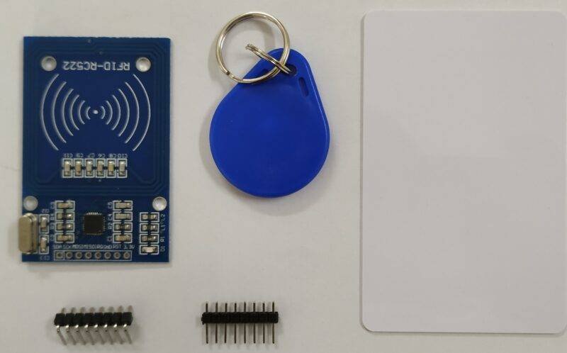
Step 1: Hardware List:
For this project, you’re going to need an Arduino/Geekduino, The RFIDuino, a compatible USB cable, and an RFID Tag of some sort. All of these things are available on the Trossen Robotics Store in a convenient kit, but you can use your own Arduino and RFID tags if you wish to. We highly recommend using the Geekduino due to the use of the manual reset toggle switch that doesn’t exist on many other Arduino variants. The rest of this instructable also assumes you will be using the RFIDuino shield and the related libraries.
- 1x RobotGeek Geekduino
- 1x RFIDuino
- 1x USB To Micro USB Cable
- 1x Thin RFID Card
- 1x Blue RFID Key Fob
- 1x Clear thin RFID lamination disk
Step 2: Familiarize Yourself With the RFIDuino
RFID stands for Radio Frequency IDentification. The RFID system consists of two components, an RFID reader and an RFID tag. The reader interacts wirelessly with a tag to retrieve a unique identification number. The system can be used for many things from opening doors to tracking inventory.
The RFIDuino Shield for Arduino adds RFID capabilities to your Geekduino/Arduino. The shield fits on top of your arduino, making solid connections to the RFIDuino’s circuitry. The built in buzzer and LEDs allow you to get stared right away by making visual and audio cues depending on the data that is on a given tag. The shield also allows you to add components to expand your system. You can use this to make your own door locks, inventory systems and more!
Step 3: Install the RFIDuino Shield
To Install the RFIduino Shield, line the pins up with the bottom of the shield and the top of the Geekduino/Arduino. The male pins on the Shield should slide into the female pins on the Geekduino/Arduino. Once the Shield is installed, you can use the included 2-pin cable to connect the Shield to the Antenna.
You can program the Geekduino/Arduino with the shield plugged in. However, you cannot program the shield if you have an XBee module plugged in. You will have to remove the module or the shield to program the Arduino.
Step 4: Get Your RFID Tag ID
In order to use our RFID tag, we’re going to need to know its ID to program into the board. Connect your RFIDuino into the computer as shown above.
You’re going to need the RobotGeek Tools and Libraries ZIP file for a sketch that will allow you to read your card data to the serial monitor. The RobotGeek Tools and Libraries Download offers a variety of sketches and libraries for working with RobotGeek Robot Kits. The libraries folder contains libraries that will add functionality to your Arduino, while the RobotGeek Sketches folder contains behavioral code for robots, as well as tools for testing. Install it by adding these two folders to your Arduino user folder.
Open the RFIDuino_helloworld sketch. This can be found under:
File>Examples>RFIDuino>RFIDuino_helloworld
You will need to make sure the code is adjusted for your RFIduino hardware.
v1.2 shields (2 pin antenna, ‘REV 1.2’ printed on the board) will need the following code
RFIDuino myRFIDuino(1.2); //initialize an RFIDuino object for hardware version 1.2
v1.1 shields (4-pin antenna, no version number printed on the board) will need the following code
RFIDuino myRFIDuino(1.1); //initialize an RFIDuino object for hardware version 1.1
Both lines of code are available in the RFIDuino_helloworld sketch, simply uncomment the one you don’t need. If you are still unsure about what hardware you are using, see this page
Connect a micro USB cable from your computer to your Geekduino
Load RFIDuino_helloworld onto your board using the upload button in the Arduino IDE.
Once loaded, you can leave your board connected to your computer — you will need this connection to power the board and to communicate with the computer
Open the Serial Monitor.
The serial monitor should be set to its default settings (‘No Line ending’, 9600 baud)
Swipe a tag across the RFIDuino antenna. The green light will light up and your buzzer will make a noise.
The Serial Monitor will display 5 numbers separated by commas. These numbers make up the ID of your tag.
Copy down these numbers for future use. It can be handy to write the ID on a sticky note and attach it to the tag.
Tags in the EM4102 protocol have 64 bits that they return to the RFID reader. 24 of these bits are used for communication / protocol information (9 header bits, 10 parity bits and a stop bit.) This leaves 40 bits, or 5 byte for the tag’s ID. The RFIDuino library returns the tag’s ID as an array that contains these 5 bytes. All of the RobotGeek tutorials will use this convention for dealing with the Tag’s ID number, displaying the tag id as 5 numbers in decimal format. However here are many ways that you can represent this number.
Step 5: Program Your Arduino for Windows Login
Download the most recent release of the Windows RFIDuino Login Software. This download includes the necessary Arduino Firmware and Windows Software for this project. Unzip the file and you should see 3 folders and 2 files.
1. Connect your RFIDuino as shown in the diagram above
2. Open RFIDuino_windows_unlock onto your board. This sketch is in the .zip file you just downloaded under:
Firmware -> RFIDuino_windows_unlock -> RFIDuino_windows_unlock.ino
3. You will need to make sure the code is adjusted for your RFIduino hardware.
v1.2 shields (2 pin antenna, ‘REV 1.2’ printed on the board) will need the following code:
RFIDuino myRFIDuino(1.2); //initialize an RFIDuino object for hardware version 1.2
v1.1 shields (4-pin antenna, no version number printed on the board) will need the following code RFIDuino myRFIDuino(1.1); //initialize an RFIDuino object for hardware version 1.1
Both lines of code are available in the RFIDuino_helloworld sketch, simply uncomment the one you don’t need. If you are still unsure about what hardware you are using, see this page.
4. Load RFIDuino_windows_unlock onto your board using the upload button in the Arduino IDE.
5. Once loaded, leave your board connected to your computer — you will need this connection to power the board and to communicate with the computer
Step 6: Setting the Reset Swtich
This is a good reason we suggested that you use the Geekduino. Once you’ve programmed your Geekduino, you will need to change one of the switches. Set the reset switch towards ‘M_RST’. This will change the board to manual reset, so that windows does not reset the board while in use. Keep in mind that if you need to reprogram your Geekduino that you will need to change the switch back to ‘AUTO’.
We do this to prevent continuous board resets. Not every board will have this issue, but we’ve included a few lines of debug code that make the board beep on startup so that you can catch it if it does. If your RFIDuino continuously or intermittently plays those beeps and you have an Arduino Uno, there’s a solder point on the board that needs to be cut in order to achieve the same result, and re-soldered when you wish to reprogram your board.
Step 7: Installing the Windows Software
1. Using the Right Files
From the .zip file downloaded earlier, you’ll need to make sure you are using the correct files for your Operating System. For 64 Bit Versions of the operating system you’ll use the files in the 64 Bit folder. For 32 Bit Versions of the operating system you’ll use the files in the 32 Bit folder.
You’ll need to edit 2 of the .txt files.
2. RFIDCredentials.txt
First open RFIDCredentials.txt. By default the file should look like this
12 133 430 45 189|user1|password1
9 23 143 56 19|user2|password2
You’ll need one line for each Key you want to use to unlock your computer. Each line contains the tag’s ID, the windows username and the windows password, each separated by the | character. So for example, if the tag’s ID is 70 0 44 22 242 and you want to unlock a windows account with the username robot1 and the password unlockRobo1 your file should look like
70 0 44 22 242|robot1|unlockRobo1
You can use multiple tags to unlock a single account, but one tag can only unlock one account.
This project also support domain based accounts. If you want to add a line with a tag ID of 67 176 120 0 45 and you want to unlock a windows account under the domain ROBONET with the username robot2 and the password unlockRobo2 your file should look like
70 0 44 22 242|robot1|unlockRobo1
67 176 120 0 45|ROBONET\robot2|unlockRobo2
As mentioned above, each tag can only unlock one account — so this means that there can be at most one line for each unique tag you are using in your system.
3. RFIDCredSettings.txt
Open RFIDCredSettings.txt. By default the file should look like this
COM=4
LEAD=ID:
TERM=\r\n
The LEAD and TERM lines represent the characters before and after each serial message from the RFIDuino. You do not need to edit these lines.
You will need edit the first line so that it matches the serial port for your Geekduino/Arduino. The serial port number for your Geekduino/Arduino is the same serial port that you use to program it, and the same serial port number we found in the Geekduino Getting Started Guide. For example, if your Geekduino/Arduino is connected to COM32, your file should look like:
COM=32
LEAD=ID:
TERM=\r\n
4. Moving Files
You you will need to copy the 3 files into your C:\Windows\System32 folder. The files are the two text files you updated and the .dll file
RFIDCredentials.txt
RFIDCredSettings.txt
RFIDCredentialProvider.dll
Just drag and drop these 3 files into the C:\Windows\System32 folder on your computer. You may need admin privileges to copy the files over. If this folder does not exist on your computer or if you have a custom Windows Installation, you may need to recompile the .dll file to work with your system.
5. Activating the Files
Now go back to your unzipped software folder and open Register.reg. You’ll get a warning — you can click ‘OK’. Now the .dll files will be activated.
If you need to remove the program, use the Unregister.reg file and then remove the 3 files from your C:\Windows\System32 folder.
Step 8: Using This Project
Now that all of the firmware and software is installed, you can use your project. Make sure your reader is plugged into your computer and reading cards (the LED will light up when a card is sensed). Now restart or lock your computer so that you are at the user screen. Note: You need to be at the user screen, the computer will not unlock if you are at an individual login screen. You should see a new user ‘RFID’. Simply swipe your card and your computer will unlock!
Now that you have the login working, play around with the position of the RFID Antenna. If this is at your desk, in most cases, the RFID Tag can be read through it, so you can hide it under the desk, behind a drawer.
Step 9: Ideas for Expanding and Improving This Project
- As noted before, your username and password are stored in an unencrypted text file. To secure this, you would need to integrate new code into the windows software.
- You may be able to add some minimal amount of security using file permissions in windows by removing accounts from the security list SYSTEM.
- The source code for the Windows Software is available here
- By default, the firmware only changes LED color depending on the read status of the card — the buzzer has been disabled for everything but the debug startup code block. You can re-enable this by looking at the other RFIDuino examples and bringing in the buzzer code.