
PLC stands for Programmable Logic Controller. It is a digital computer used to control industrial machines. All the manufacturing industries, like the textile industry, food manufacturing plants, chemical industry, oil and gas sector, etc., use PLC to automate the production process. It uses the following programming languages:
- LLD (Ladder Logic Diagram)
- FBD (Functional Block Diagram)
- SFC (Sequential Function Chart)
- ST (Structured Text)
- IL (Instruction List)
The first three are the graphical languages and the last two are the text languages. If you are an engineering student and pursuing a course in PLC, this article will be beneficial for you because here, you will find the best free PLC simulation software to run on your PC.
PLC Simulation software for Windows 11/10
You can download these software on your Windows PC and practice by creating different logic diagrams. The best part of these software is that you do not require any external PLC hardware to run the simulation.
We have the following software on this list:
- OpenPLC Editor
- i-TRiLOGI
- WPLSoft
- Do-more Designer
- WTE PLC Configuration Tool.
1] OpenPLC Editor

OpenPLCEditor is a freeware that is loaded with lots of features. It is a portable software, which means you need not install it on your PC. It is downloaded in the zip file. After extracting the zip file, open the respective folder and click on the “OpenPLC Editor” shortcut file to launch the software. It will take some time to open depending on the processor of your computer.
It offers you to write a program in any of the 5 PLC programming languages. To start a new project, click on “File > New.” Then write the name of your project and select the programming language and click “OK“. Do note that you have to create a new empty folder on your PC every time you create a new project. All the programming functions like on/off buttons, timers, counters, functional blocks, numerical operators, comparative operators, etc., are available on the right panel of the software.
Steps to draw a ladder diagram:
- To create a ladder diagram, first, you have to define all the variables and their types like boolean, integers, real, arrays, byte, word, etc. Click on the “Plus” icon in the middle panel. You can also set the initial value of all the selected variables.
- Right-click in the middle space, then click on “Add” and select power rail. This will add the rail on the screen.
- Follow the above step to add input contact variables, output coils, blocks (for the timer, counter, etc.), comments, etc.
When you are done, click on the “Start PLC Simulation” button on the toolbar. When you hover your cursor, you will see the names of all tools on the toolbar. If your ladder logic has any error, it will be displayed in the red color in the console tab. You can click on the PLC log tab for more details about the error. After clicking on the “Start Simulation,” you have to click on the “Debug instance” button in the bottom left panel and the simulation will be started. To perform an action like turning the switch ON, right-click on it and select “Force True.” To save your project, click on the “Save” button or press “Ctrl+S.”
2] i-TRiLOGI
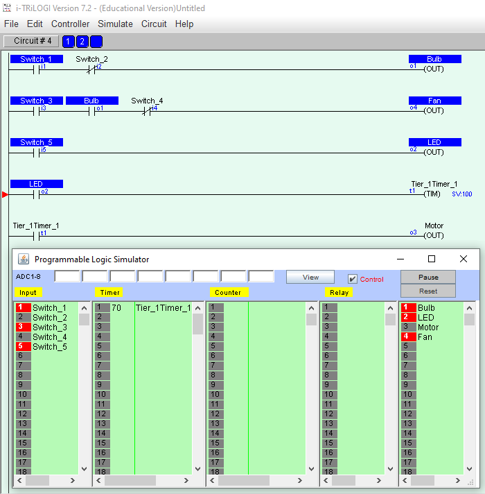
i-TRiLOGI is another freeware on this list by which you can practice ladder logic programming. The process of downloading this software is different. We have provided the link to their official website. After landing on their official website, fill the form provided and they will send you a download link on your email ID along with a password for installation. This software is completely free for educational purposes. The best part of the software is that it has a user-friendly interface and you will understand it easily.
After installing it, if you do not get its shortcut on the desktop, go to “C Drive > TRiLOGI Folder > TL7Edu Folder.” There you will get the exe file. Click on that file to run the software.
Steps to draw a ladder diagram:
- Like OpenPLC Editor, here, you also have to define the variables first. For this, click on “I/O Table” on the toolbar, select the I/O label from the drop-down menu. You can define inputs, outputs, timers, counters, relays, etc.
- After defining the variables in the I/O table, click on “Circuit > Insert Circuit” to add a rung. If you add contacts by left click, you will get Normally Open (NO) contacts and vice versa. Alternatively, you can also toggle the contacts by clicking on the respective button on the toolbar.
To start a simulation, go to “Simulate > Run (All I/O Reset).” You can change the values of the variables in the circuit by right-clicking in the simulation table. Click on the “Pause” button to stop the simulation. Go to “File > Save” or press the “Ctrl + S” buttons to save your project.
3] WPLSoft
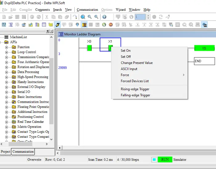
WPLSoft is a free PLC simulation software from Delta Electronics. If you do not find the software on the website, write WPLSoft in the “Keywords” section and select the highest version, then click on the “Submit” button.
WPLSoft is a fully-featured free PLC simulation software. You will find all the ladder logic functions here, such as bit logics (NO, NC, set coil, normal coil, reset coil), mathematical operators, timers, counters, comparators, hi-speed comparators, etc. If you are a working professional, you can download your project in Delta PLC by using this free software.
Steps to draw a ladder diagram:
- WPLSoft has a very simple user interface. First, create a new project by pressing the “Ctrl + N” button.
- All bit logic operations, like NO (Normally Open), NC (Normally Closed), coil, etc., are available on the toolbar. Click any of them to select.
- Now, define the address of your selected function and click on OK.
Unlike other software, here, you cannot start the simulation with just one click. First, you have to click on the “Simulation” button on the toolbar. You can read the names of each button by hovering your mouse cursor. After that, click on “Write to PLC” or press “Ctrl + F8.” A popup window will appear, click on OK to compile the program. Then, click on the “Ladder Start Monitoring” or press the “L” button. At last, click on the “Run” button or press “Ctrl + F11” and select “Yes.” This will start the simulation. To change the bit value, select it and press the right click of your mouse and select the desired option. To save the project, go to “File > Save” or press the “Ctrl + S” buttons.
4] Do-more Designer
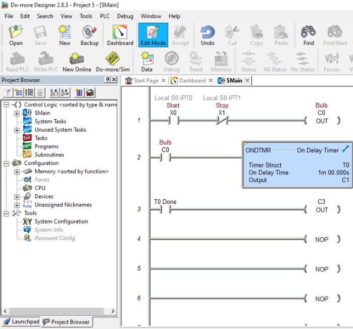
Do-moreDesigner is one more freeware in this list to simulate PLC ladder logic programming instructions. Like other PLC simulation software on this list, this one also comes with a user-friendly interface. You will find all the programming variables on the right panel of the software, including contacts (NO, NC, output coils, leading-edge, etc.), comparators, timers, counters, mathematical operators, strings, and more.
Steps to draw a ladder diagram:
- Go to “File > New Project > Offline Project” or simply press “Ctrl + N” keys. If the software asks you to select a PLC from the list, select Do-more Simulation because you do not have PLC hardware.
- Place the input and output variables on the rung from the right panel by the drag and drop method.
- Now, double-click on the placed variable and define its address. Here, X denotes the input and C denoted the output. When you are done, press “Ctrl + S” to save your project.
Defining the time in Do-more Designer’s timer is very easy. You will get different sections of hours, minutes, seconds, and milliseconds. Hence, you can enter the desired value easily.
To start the simulation, click on the “Accept” button on the toolbar. Then click on the “Do-more/Sim” button on the toolbar. It will launch a simulator window. Use this window to control your PLC program.
5] WTE PLC Configuration Tool
WTE PLC Configuration Tool is a free PC simulation software that comes with a simple user interface. You can use it to design simple to complex ladder diagrams. Timers, counters, comparators, memory bits, etc., are also easily accessible. After designing a PLC ladder logic diagram, you can run the simulation and view the output on the right pane. To download WTE PLC Configuration Tool, visit its official website.
Did we miss your favorite?
4 Best Free PLC Software For Windows
Here is a list of best free PLC software. Some of these software can be used for industrial purposes, while some can be used for both educational and industrial purposes. These free software help you learn the basics of PLC programming. You can learn Ladder Logic Language, Sequential Text Language, etc. using these PLC software.
Some of these PLC software are specially designed for beginners, so that they can practice Ladder Logic language (basic PLC programming language). You will find all necessary programming instructions in some of these freeware, while some come with only basic instructions list. All these freeware are best to learn the basics of Normally Opened and Normally Closed contacts, as these sometimes become the most confusing part of PLC programming. Apart from this, there are other Ladder Logic instructions, like: Timers, Counters, Relays, Analog I/Os, Math functions, Comparators, etc. Besides these, High-Speed Timers and High-Speed Counters are also available in some of these software.
If I categorize these free PLC software on the basis of Simulation, some of these are software with inbuilt PLC Simulator. With the help of simulation, you can examine a written PLC program in real time. From education perspective, PLC simulation is a very important feature of a PLC software, as it helps you analyse every rail in a rung. While analyzing a program in real time, you could know, what is going on in your designed Ladder Logic.
In this list, you will also find one Allen Bradley PLC software.
My favorite free PLC software:
I like PSIM PLC Training Simulator. This is the only software in this list that comes with pre-designed process animations. It is developed by one of the leading firms in industrial automation, Allen Bradley. Here, you will find process animations of Traffic Light, Batch Mixer, and more. Besides these, On-Delay Timer, Retentive Timer, Up-Counter, Down-Counter, most of the Bit Logics, Comparators, Math Functions, etc. are also available.
Go through the list and install these free PLC software on your PC and start practicing PLC programming.
You may also like some of the Circuit Design Software, Circuit Simulation Software, and Oscilloscope Software for Windows.
PSIM PLC Training Simulator
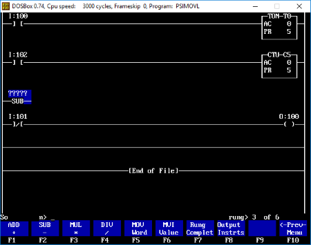
PSIM PLC Training Simulator is a free Allen Bradley PLC software. This PLC simulator for students not only lets you simulate PLC circuits, but also helps you learn PLC programming. It comes with built-in PLC simulator that lets you analyze PLC program in real-time.
It is one of a kind in this list; unlike HMI and SCADA where you have to design animation, you will find pre-designed animations here. Only four types of animations are provided in this software. You can operate them as per your designed Ladder Logic. Let’s have a look at some of these process animations:
- I/O Simulator: This is a very basic simulation provided in this Allen Bradley PLC simulator. I/O simulator is designed to clear your basics on NO and NC, i.e. Normally Opened and Normally Closed contacts. This PLC simulator contains digital inputs and outputs. The interface of this PLC software looks like basic architecture of PLC. You will find digital inputs on its left side and digital outputs on its right side. The middle part contains Data Table, where you can view real-time values of all digital inputs, digital outputs, timers, and counters by executing a written program. Two types of digital inputs are provided in the software: Push buttons and Toggle switch. It can display input and output values in binary, decimal, or hexadecimal form. To make a Ladder Logic program, simply press F5 function key on your keyboard and you will be on the programming screen of the software.
- Traffic Light: This is a traffic light simulator. In this process animation, you will find a traffic light with 6 outputs. Enter into the programming window by pressing F5 key and design a Ladder diagram which can simulate this traffic light correctly.
- Batch Mixer: It is a Batch mixing simulator. You can perform the process automation of a Batch mixing plant here. Animation of Batch Mixer is designed in such a way that it looks like an original Batch mixing plant. The inputs and outputs provided in this process animation include: Mixer, Heater, Ultrasonic sensors, Solenoid valves, etc.
You will find all necessary instructions to create a Ladder Logic program. From digital I/Os to timers and counters, from comparators to math functions, all instructions are available in this free PLC simulation software, even On-Delay timer, Retentive timer, Up-Counter, and Down-Counter are also provided in the software. Defining address to your instructions is also very simple. You can enter preset values of timers and counters easily. Unlike some PLC software, there is no need to enter preset time in coded instruction. Just enter a value and it accepts that value. For example, if you want a time delay of 10 seconds in your program, just enter 10 as its preset value.
This is one of the best PLC programming software in this list and is only PLC software that comes with process animations.
NOTE: This is a PLC simulator software and is only developed for education purposes. You cannot use this software to download a PLC program in a PLC.
i-TriLOGI
i-TriLOGI is a free PLC Simulator software for PC. Thanks to its built-in PLC Simulator that lets you simulate a written PLC program in real time, you can learn the basics of PLC programming and practice it. You can also find out if a program is working properly or not with the help of this feature.
Do note that the free version of this PLC Simulation software is designed only for educational purpose. If you want to use it for commercial purpose, you will have to purchase its full version.
In the free version, you will find only a limited PLC instructions, that are good to learn basics of Ladder Logic programming language. You will find Normally Opened contacts, Normally Closed contacts, Timers, Counters, Relays, and many other instructions to design a Ladder diagram.
Interface: It comes with a simple UI, which makes it easy to understand. You can place multiple rungs on a rail. A single click on a rung opens a list of Ladder Logic instructions, from where you can easily select an instruction to draw a Ladder diagram. Configuring timer and counter is also very easy in this PLC simulation software. For example, if you want to define 5 counts, then simply select a counter and enter the number of counts, that is 5. That’s all.
Simulate: This feature lets you examine a designed Ladder diagram in real time. It doesn’t matter whether you have a PLC or not. It lets you run a PLC program without connecting it with PLC. It also lets you change the state of a contact (NO or NC) in simulation mode. It executes your program in simulator mode just like a real PLC scans, i.e. from left to right and from top to bottom.
Advantages of i-TriLOGI:
- Simple user-interface.
- Addressing I/Os is simple.
- It lets you add comments to each I/O.
- You can take a printout of your program.
Limitations of this free PLC Simulator:
- Only On-Delay timer is provided in the software. I did not find On-Delay Retentive and Off-Delay timers.
- Only digital I/Os are available in the software. It lacks Analog I/Os.
- I did not find any comparators in the software.
- Other necessary instructions like move, convert, PID, etc. are also missing in this free PLC Simulator.
- This free version of i-Triologi doesn’t let you connect a PLC to your system.
NOTE: You have to create a free account on its official website in order to download it.
WPLSoft
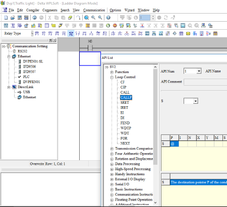
WPLSoft is a free PLC programming software from Delta electronics. This PLC software is good for students as well as working professionals. You can carry out all industrial automation processes with this free Ladder Logic software. You can use this free PLC software only for Delta PLCs. Draw a Ladder diagram in this freeware and download it in Delta PLC. Don’t worry if you do not own a delta PLC; it comes with a built-in PLC simulator, which lets you examine your program in real-time. You can go online and view what is happening with your designed PLC program.
Talking about the interface, it is kept simple, so that you can easily use it. You will find all the instructions needed to write a simple or complex PLC programs. All bit logic such as NO, NC, Positive Edge, Negative Edge, Coil, Set Coil, Reset Coil, etc. can be found here. Other than bit logic, Math functions, Comparators, Timers, Counters, High-Speed Counters, etc. are also available in this software.
Advantages of this free PLC Software:
- Simple user-interface.
- You can easily configure PLC-Drive communication.
- Defining Address is simple.
- You can also define a tag name in this software, like START, STOP, MOTOR ON, MOTOR OFF, etc.
- Use its simulation mode to view your program in real-time.
- Program comparison feature is available.
- It supports three PLC programming languages: Ladder Logic, STL (Sequential Text Language), and SFC Diagram.
You can use this software in Servo Motion control applications. It lets you control Servo Motor at particular axes.
Micro LADDER
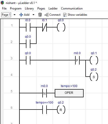
Micro LADDER is another free PLC software in this list. This PLC freeware is designed for Sirea PLCs. This means, you can only use this free PLC software with Sirea Programmable Logic Controllers. As it comes with a free license, you can use it for developing a Ladder Logic program.
Features offered by this free PLC software:
- Data: You will find all types of data (instructions) in this software. Digital inputs, digital outputs, analog inputs, analog outputs, PWM outputs, system bits, system words, etc. are provided in this free PLC software.
- Programming languages: This free PLC software comes with two programming languages: Ladder Logic and C. Unlike popular PLC software, like TIA (SIEMENS), RSLogix (Rockwell), etc., it lacks other PLC programming languages, such as Sequential Text Language, Functional Block Diagrams, etc.
- Page: It lets you create a page and call it in your main block of PLC program, just like Functions and Functional Blocks can be called in main Organization Block in SIEMENS PLC software.
Communication: It uses MODBUS communication. You can establish a Master and Slave MODBUS communication using this free PLC software.
Addressing: Defining address to instructions is very easy in this free PLC software. Use I for digital inputs, Q for digital outputs, IW for analog inputs, and QW for analog outputs. For example, I3.0 means first bit of 3rd byte. If you type QW10, then it covers 9th and 10th bytes of PLC memory.
LCD Screen: Some of the Sirea PLCs come with built-in LCD screen on which you can display messages by writing some text. You can configure that text only in C language by writing instructions. Besides this, you can also display date and time on LCD screen.
Some general features of this free PLC software:
- It lets you save and load a program.
- You can import and export firmware into and from the software.
- Import and Export GUI features are also available in Micro LADDER.
NOTE: There is no PLC simulator in this PLC software.
In the evolution of industrial science, simulation, and emulation has become vital for virtual commissioning processes. Testing of real-world automation systems could be done virtually, mimicking a real automation system. This project documents current thinking on creating simulation and emulation models to provide feedback to industrial PLC programs to test their logical operation before commissioning.
Both approaches are trying to create the same output as in a real-world automation system. Still, with emulation, testing of PLC programs goes a step further by minimizing the gap between reality and the virtual world.
The simulation can be used in a demonstration of a real industrial process functionality and for testing the control algorithm on interactive realistic models of machine tools in the VR environment, while the real programmable logic controller controls the industrial process.
VIRTUAL CONTROL
VC projects are performed to verify PLC programs in a simulation environment before the physical implementation for which all resources are modeled virtually without any risk of endangering lives and equipment. Testing of PLC programs can provide decision-making support for different engineering fields and real-time communication between PLC and the simulation model.
A VC project involves three distinct factors:
- Mechatronic design including actuators, sensors, and functional descriptions.
- Machine control including inputs and output signals.
- Connection between sensors, actuators, and the control program.
PLC Simulators
PLC (Programmable Logic Controller) simulation and virtualization tools are essential for testing, developing, and simulating industrial automation processes without the need for physical PLC hardware. Here are some popular tools used in the industry:
RSLogix Emulator:
This is a software emulator for the Allen-Bradley line of PLCs, allowing you to test and debug ladder logic programs without physical hardware.
RSLogix 5000 Emulator software acts as a PLC CPU, it does not have any input/output modules. In most cases, this is sufficient to test the code and make sure the SCADA clients can receive/send data from/to PLC.
Siemens PLCSim:
Simulates the S7-1500, S7-1200, and other Siemens PLCs. It integrates with the TIA Portal (Totally Integrated Automation) for comprehensive simulation and testing.
With the SIMATIC S7PLCSIM Advanced virtual controllers for the simulation of a S7-1500 or ET 200SP CPU are created and used for the comprehensive simulation of functions. Therefore no real controllers are required to test a STEP 7 program.
The virtual controllers can also be tested in the context of a system or machine. The user interface (API) is used to connect the virtual controller to a system or machine simulation (co-simulation). A STEP 7 program created in STEP 7 V14 controls a conveyor system.
For a comprehensive function test, the STEP 7 program is loaded via S7-PLCSIM Advanced into a virtual S7-1500 controller. This controller interacts via the API with a co-simulation (plant simulation), to validate the STEP 7 program in the context of the plant.
Virtual PLC Software
Virtual PLC software offers a digital platform for designing, simulating, and testing PLC programs without the need for physical hardware. This powerful tool enables engineers and students to develop and refine automation solutions efficiently, reducing costs and minimizing risks associated with physical prototyping.
By providing a virtual environment to experiment with different PLC configurations and logic, users can accelerate the development process, enhance troubleshooting capabilities, and gain a deeper understanding of PLC operation. In the following sections, we will explore a variety of virtual PLC software options available in the market
TwinCAT (Beckhoff)
Offers a complete virtualization environment for Beckhoff PLCs. It supports real-time simulation and can be used for both PLC and PC-based control systems. It supports the creation of a virtual machine, which corresponds to a real one in its runtime performance.
The task of the TwinCAT Simulation Manager is essentially to break and restore links, such as between a PLC variable and an IO point. In the case of simulation, the link is broken and reconnected to a simulation environment.
Codesys Virtual PLC
Allows you to simulate PLC programs created with the Codesys development environment. It supports various PLC hardware configurations and protocols.
CODESYS Virtual Control has no hardware requirements.CODESYS provides hardware-independent Soft PLCs with and without real-time for Windows, as well as Soft PLC solutions for Linux x86 and ARM-based systems
MATLAB/Simulink
Provides simulation capabilities for control systems, including PLCs, with extensive support for modeling and simulation of industrial processes.
Simulink PLC Coder generates hardware-independent IEC 61131-3 Structured Text and Ladder Diagrams from Simulink models, Stateflow charts, and MATLAB functions.
Structured Text is generated in PLCopen XML and other file formats supported by widely used integrated development environments (IDEs), including 3S-Smart Software Solutions CODESYS®, Rockwell Automation Studio 5000, Siemens TIA Portal, and Omron® Sysmac® Studio.
Ladder diagrams are generated in file formats supported by Rockwell Automation Studio 5000. As a result, you can compile and deploy your application to numerous programmable logic controller (PLC) and programmable automation controller (PAC) devices.
https://www.mathworks.com/products/simulink-plc-coder.html/
Automation Studio (B&R)
Offers simulation tools for PLC programming, motion control, and HMI development. It supports the virtual commissioning of automation systems.
List of Generic PLC Simulation Tools
- Festo FluidSIM:
Simulates pneumatic and electro-pneumatic control systems, which are useful for testing PLC programs that interact with such systems. - LabVIEW:
While primarily a data acquisition and instrumentation software, LabVIEW can also simulate PLC behavior through its Real-Time Module.
Cloud-Based PLC Simulation
- COSIMIR Industrial (from KUKA): Provides cloud-based virtual commissioning and simulation for industrial automation systems, including PLCs.
These tools enable engineers and developers to validate PLC programs, simulate control strategies, troubleshoot potential issues, and test new configurations in a virtual environment before deploying them in industrial settings.
Each tool may vary regarding supported PLC brands, simulation features, and integration capabilities with other automation software.
Fathima Sadina works as a Technical Associate at IIPD, where she dives into the world of Industrial Automation, focusing on PLC, SCADA, and VFD systems. With a keen passion for spreading know-how, she loves to craft engaging blog posts on a wide array of technical subjects.
Это приложение для Windows под названием PLC simulator, последний выпуск которого можно загрузить как PLCSimulator_20090402.zip. Его можно запустить онлайн в бесплатном хостинг-провайдере OnWorks для рабочих станций.
Загрузите и запустите онлайн это приложение под названием PLC simulator с OnWorks бесплатно.
Следуйте этим инструкциям, чтобы запустить это приложение:
— 1. Загрузил это приложение на свой компьютер.
— 2. Введите в нашем файловом менеджере https://www.onworks.net/myfiles.php?username=XXXXX с желаемым именем пользователя.
— 3. Загрузите это приложение в такой файловый менеджер.
— 4. Запустите любой онлайн-эмулятор OS OnWorks с этого сайта, но лучше онлайн-эмулятор Windows.
— 5. В только что запущенной ОС Windows OnWorks перейдите в наш файловый менеджер https://www.onworks.net/myfiles.php?username=XXXXX с желаемым именем пользователя.
— 6. Скачайте приложение и установите его.
— 7. Загрузите Wine из репозиториев программного обеспечения вашего дистрибутива Linux. После установки вы можете дважды щелкнуть приложение, чтобы запустить его с помощью Wine. Вы также можете попробовать PlayOnLinux, необычный интерфейс поверх Wine, который поможет вам установить популярные программы и игры для Windows.
Wine — это способ запустить программное обеспечение Windows в Linux, но без Windows. Wine — это уровень совместимости с Windows с открытым исходным кодом, который может запускать программы Windows непосредственно на любом рабочем столе Linux. По сути, Wine пытается заново реализовать Windows с нуля, чтобы можно было запускать все эти Windows-приложения, фактически не нуждаясь в Windows.
СКРИНШОТЫ

Симулятор ПЛК
ОПИСАНИЕ
Аудитория
Разработчики
Интерфейс пользователя
Интернет, Win32 (MS Windows)
Язык программирования
JavaScript, VBScript
Категории
HTML/XHTML, человеко-машинные интерфейсы, моделирование
Это приложение также можно загрузить с https://sourceforge.net/projects/plcsimulator/. Он размещен в OnWorks, чтобы его можно было легко запускать в Интернете с помощью одной из наших бесплатных операционных систем.
Скачать приложения для Windows и Linux
- Приложения для Linux
- Приложения для Windows
-
1
- D3.js
- D3.js (или D3 для документов, управляемых данными)
это библиотека JavaScript, которая позволяет вам
для создания динамических интерактивных данных
визуализации в веб-браузерах. С D3
вы… - Скачать D3.js
-
2
- Shadowsocks
- Быстрый туннельный прокси, который поможет вам
обход брандмауэров Это приложение
который также можно получить из
https://sourceforge.net/projects/shadowsocksgui/.
Это ха … - Скачать Shadowsocks
-
3
- Темы GLPI
- Скачать выпуск на
https://github.com/stdonato/glpi-modifications/
Цветовые темы для GLPI 0.84 и 0.85 Новое
Модификации для GLPI Это
приложение, которое c … - Скачать темы GLPI
-
4
- SMPlayer
- SMPlayer — бесплатный медиаплеер для
Windows и Linux со встроенными кодеками
который также может воспроизводить видео с YouTube. Один
из наиболее интересных особенностей
SMPlayer: … - Скачать SMPlayer
-
5
- AAX в MP3
- Использование: — Установка Audible Manager.
и откройте файл своей учетной записи. — Подписать
в ваш звуковой аккаунт (в
заявление). Теперь программа может
преобразовать вас … - Скачать AAX в MP3
-
6
- TestLink
- TestLink — это веб-система управления тестированием.
инструмент. Приложение предоставляет тест
спецификации, планы испытаний и их выполнение,
Отчетность, Спецификация требований
и … - Скачать тестСсылка
- Больше »
Команды Linux
-
1
- 4s-кластер-стопJ
- 4s-cluster-stop — Остановить серверные части на
КБ в кластере. … - Запустите 4s-cluster-stopJ
-
2
- 4s-импортJ
- 4s-import – Импортируйте RDF в 4store KB.
… - Запустите 4s-importJ
-
3
- копт
- копт — глазок-оптимизатор СИСНОПИС:
копт файл.. ОПИСАНИЕ: копт
оптимизатор глазка общего назначения. Это
считывает код со стандартного ввода и
пишет … - Беги коп
-
4
- база данных копирования-1.3
- copydatabase — выполнить
подокументная копия одного или нескольких
Базы данных Xapian … - Запустите базу данных copydatabase-1.3.
-
5
- g3toxwd
- g3toxwd — конвертирует факсимильный файл группы 3
в отображаемый файл xwd… - Запустите g3toxwd
-
6
- g15композитор
- g15composer — скриптовая команда
интерфейс для рисования libg15render(3)
функции ОПИСАНИЕ: G15composer — это
скриптовый командный интерфейс к
libg15рендер … - Запустите g15composer
- Больше »
A ladder logic simulator is a software application that lets you simulate the operation of a PLC ladder diagram with a personal computer, mobile phone or tablet. It allows you to test your PLC ladder diagram without the need to purchase any PLC hardware.
A ladder logic simulator also has the ability to control the state of the inputs, outputs and internal variables. This means that input and output devices do not need to be purchased or connected to the PLC.
You can save time and money by using a ladder logic simulator to test your ladder diagram.
Saving 100’s, even 1000’s of dollars on purchasing a PLC sounds like a good idea. Especially if you are just starting out on the journey to learn ladder logic programming.
Ladder Logic Simulator Free Download
The Do-more Designer PLC Programming Simulator is by far the easiest, most flexible, feature packed ladder logic simulator that’s out there at the moment for a PC.
It’s free to download with no registration required and genuinely no strings attached.
The Do-more Designer is actually the PLC programming software used for the Do-more PLC by Automation Direct.
The actual PLC Programming Simulator is built into the Do-more Designer software and is a full-featured programming tool, not just a demo version.
The beauty of using actual PLC programming software with a built in PLC simulator is that it allows you to get a feel for what real PLC programming software is like.
So when you transition to using real life PLC hardware the learning curve is much easier. Even if you are using different PLC hardware.
The Do-more Designer Software is compatible with Windows Vista, Windows 7, Windows 8 and Windows 10 operating systems.
The minimum system requirements are a 1GHz single core CPU with 1GB RAM and 330Mb of storage.
To get the Do-more Designer PLC Ladder Logic Simulator Free Download from Automation Direct click here.
Once you’ve installed the software it’s time to get stuck into a PLC ladder logic simulator example.
Let’s do a ladder logic latch example with the PLC simulator.
For an explanation on ladder logic latch programming click here.
Create a New Project To Use With the PLC Simulator
Run the application and choose New Offline Project….
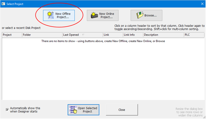
If the “Select Project” dialog box does not automatically pop up then go to File, New Project and select Offline…
In the “New Offline Project” dialogue box select “Do-more Simulator” in the Do-more Hardware Class. Then name the project, select the directory location and click OK….
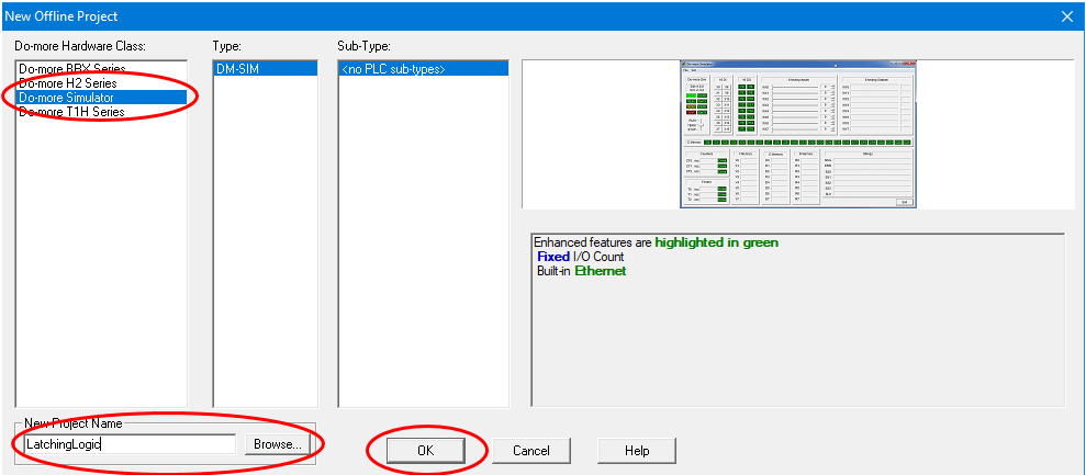
Well done. We have just created a new project file for the PLC simulator.
PLC Simulator Layout
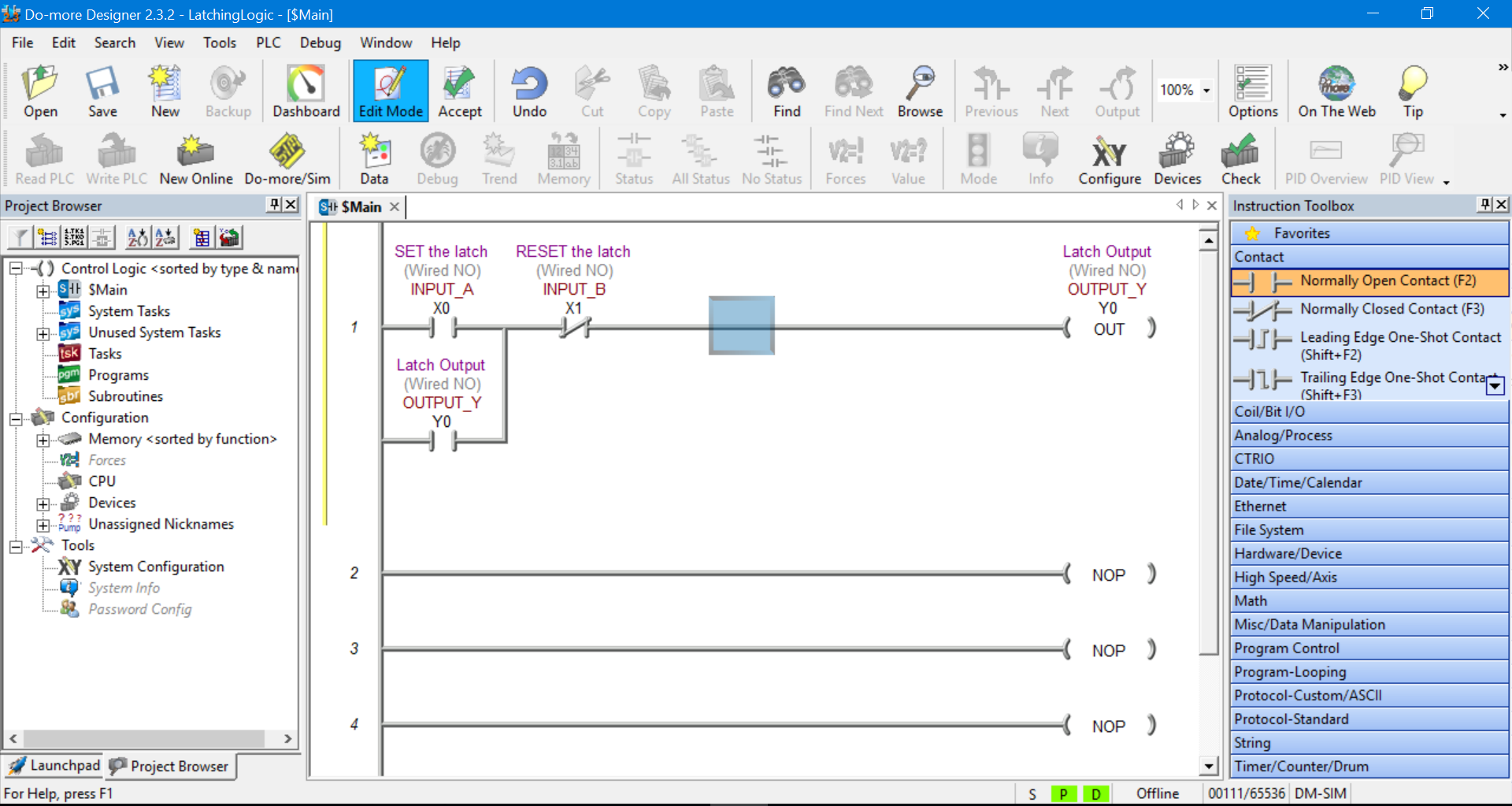
When your newly created project first fires up the layout should be similar to below….
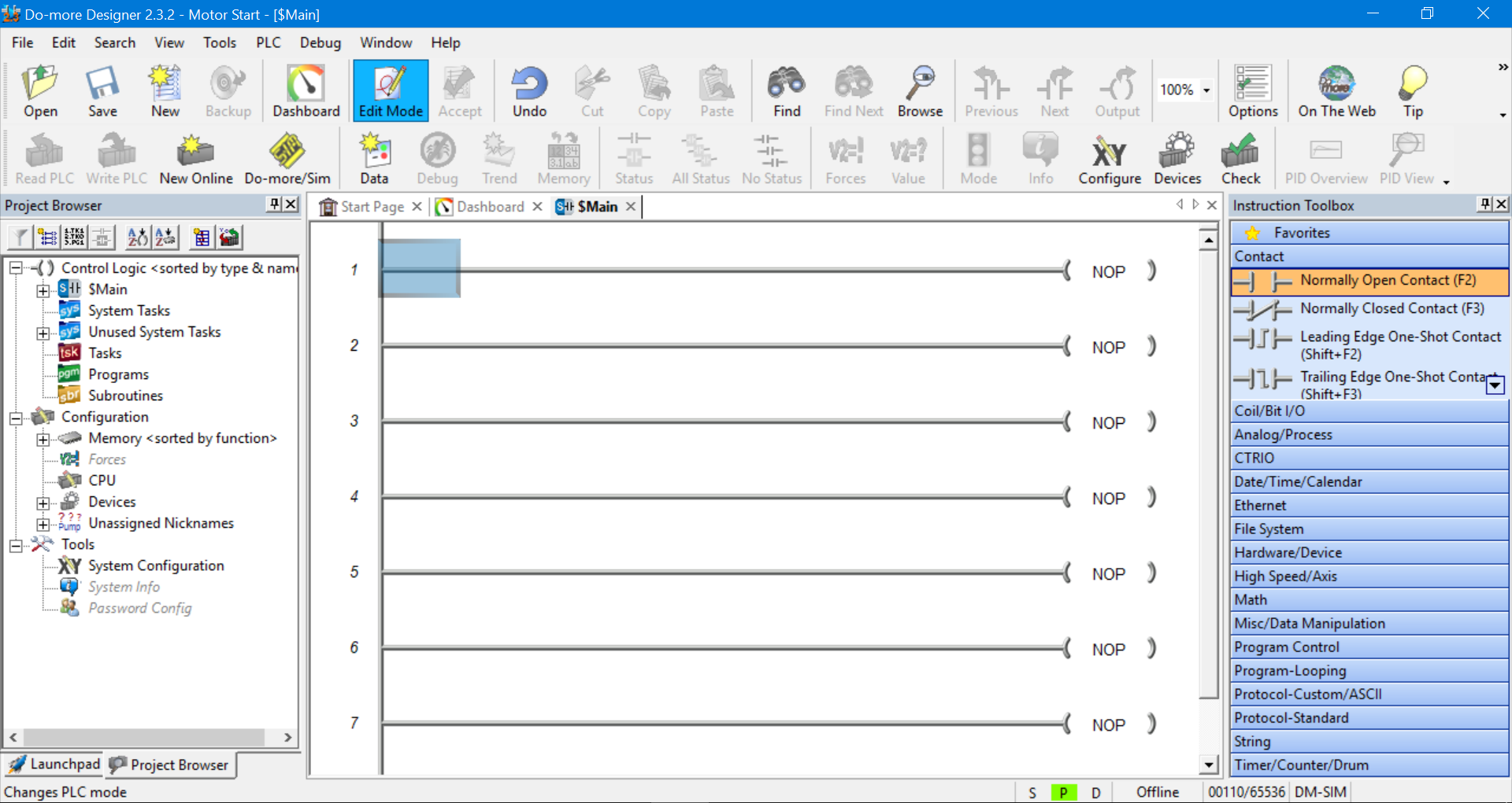
The Main Toolbar is at the top, the Project Browser is on the left, the Instruction Toolbox is on the right and the Status Bar is down the bottom.
The Main Toolbar and Project Browser can be hidden or made visible by selecting the View menu in the Main Toolbar. And the Instruction Toolbox can be hidden or made visible by selecting the Edit menu in the Main Toolbar.
We should have the Main program displayed. It will have a bunch of rungs connected to NOP (no operation) outputs.
We can close the Dashboard and Start Page tabs (next to the Main tab) to simplify things.
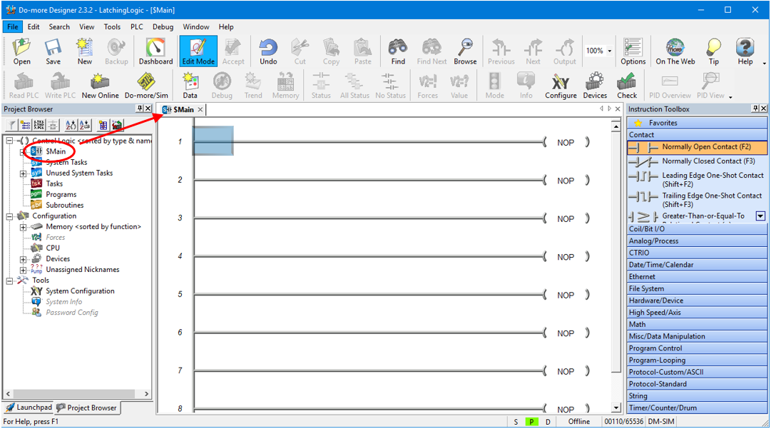
If you accidentally close the Main program just double click on “Main” in the Project Browser on the left hand side…
The Do-more Designer is fully functional PLC programming software. There is an awful lot that we can do with this kind of software with regards to structuring and organizing our program.
Because we are using the PLC programming simulator we will be limited to the amount of ladder logic programming that we can simulate at any one time. So we don’t need to fully utilize all of the software’s features.
We will only need to do our ladder logic programming in the Main program. There is no need to create extra programs or sub routines at this stage. We’ll stick to the essentials for now.
Using the Ladder Diagram Editor
So let’s get started with our first piece of ladder logic programming.
If Edit Mode is not highlighted in the Main Toolbar then click on it to enable program editing….
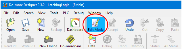
This will also pop up the Instruction Toolbox on the right hand side.
Please note that the Do-more PLC simulator calls a symbol an instruction. Don’t worry, the two terms, instructions and symbols, are readily interchangeable.
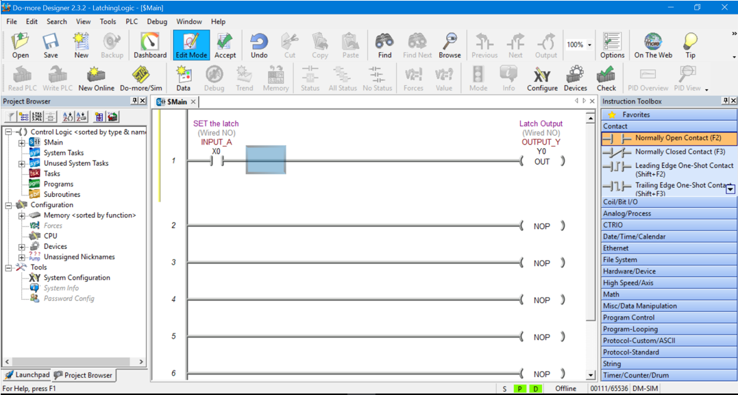
Grab a Normally Open contact symbol (or instruction) from the Instruction Tool bar and drag and drop it into the start of the first rung….
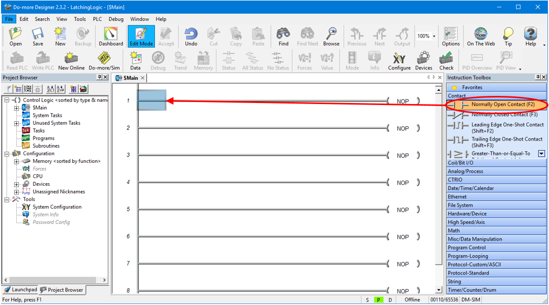
If we drop the instruction in the wrong spot or have accidentally dropped the wrong instruction then we can cancel it by hitting the ESC key.
If we have already declared the symbol and want to delete it then select the symbol and hit the Delete key.
A dialogue box will popup so we can declare the symbol.
PLC Simulator Input Symbol Declaration
The Do-more PLC programming simulator allocates symbol addressing the same as the actual real life PLC.
In this example we will be declaring digital inputs and digital outputs as per below….
X0-2047 (Digital Inputs)
Y0-2047 (Digital Outputs)
Because this PLC simulator is fully featured there are other symbol declarations possible, but we will not be using them for this example….
C0-2047 (Digital Internal Variables)
RX0-255 (Real Analog Inputs)
WX0-255 (Signed Word Analog Inputs )
RY0-255 (Real Analog Outputs )
WY0-255 (Signed Word Analog Outputs
R0-2047 (Real Internal Analog Variables)
V0-2047 (Unsigned Word Internal Analog Variables)
N0-2047 (Signed Word Internal Analog Variables )
D0-2047 (Signed Double Word Internal Analog Variables)
T0-255 (Timers )
CT0-255 (Counters)
ST0-1023 (System Variables)
To declare the instruction as a digital input type X0 into the text field and click on the magnifying glass icon. Don’t worry about the yellow popup box for now, you can close it if you want….
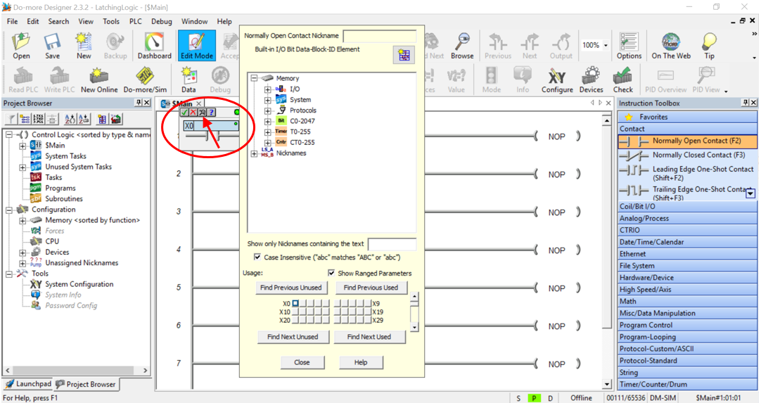
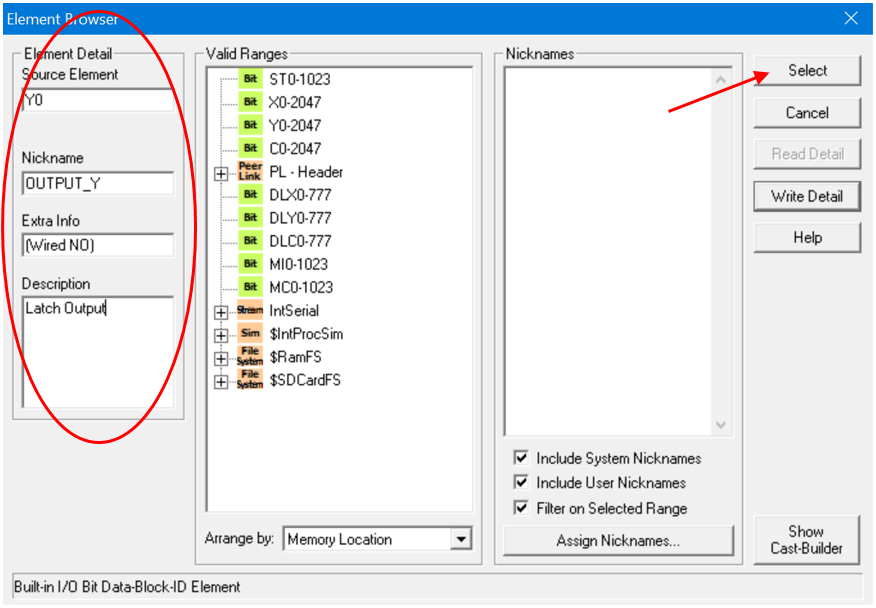
After the magnifying glass icon is selected the Element Browser table will popup. Fill it in as per below….
And then click Select.…
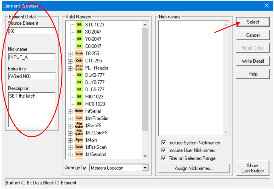
Save the changes when prompted.
Then click on the tick icon to accept the instruction declaration…
Now, the first rung of the ladder diagram should have the normally open contact with all the declared information displayed above it, as per below…..

PLC Simulator Output Symbol Declaration
So let’s add an output to the first rung.
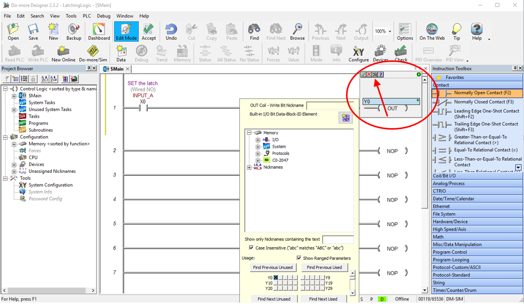
Double click on the NOP output on the right hand side of the first rung. The instruction declaration pop up box appears.
This time we need to declare an output address, so type Y0 into the text field. Then click the magnifying glass….
After the magnifying glass icon is selected the Element Browser table will popup. Fill it in as per below….
And then click Select.…
Save the changes when prompted.
Then click on the tick icon to accept the instruction declaration…
The first rung of the ladder diagram should now have the normally open contact in series with the output. All the declaration information should be displayed above each ladder logic symbol….
Adding More Symbols Using the Ladder Diagram Editor
Let’s continue with adding the rest of the ladder diagram symbols for the Latching logic.
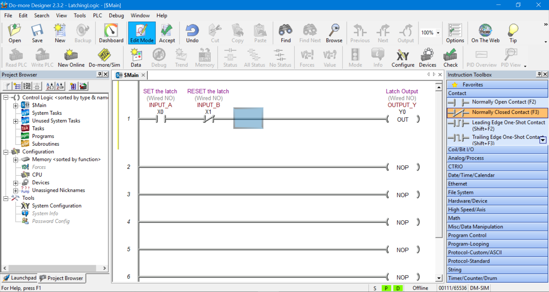
This time we need to drag and drop a normally closed contact into the position next to INPUT A.
Use the same procedure as above to declare the instruction. This time declare it as input X1 as per the information below…
Remember to click Select, Save the changes if prompted and then click on the tick icon to accept the instruction declaration.
Now we’re cooking. The Main program should look like this….
Adding a Symbol Branch Using the Ladder Diagram Editor
Time to add the last ladder diagram symbol to complete our ladder logic latch PLC simulator example.
Grab a normally open contact and drag and drop it into the area just below the INPUT A symbol.
This symbol has already been declare so we do not need to declare it again. Just enter Y0 in the instruction declaration text box and hit the tick icon or press enter.
The Main program should look like this….
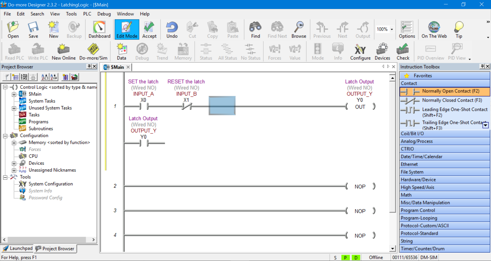
Notice there is a connection missing between the new symbol just added and rung 1.
We can add that connection by clicking on INPUT B symbol to select it. Then going to the main toolbar and selecting Edit, Wire and the Down.
This will create a connection from rung 1 down to the end of Output Y normally open contact. Thus creating a branch (or parallel) connection across INPUT A normally open contact….
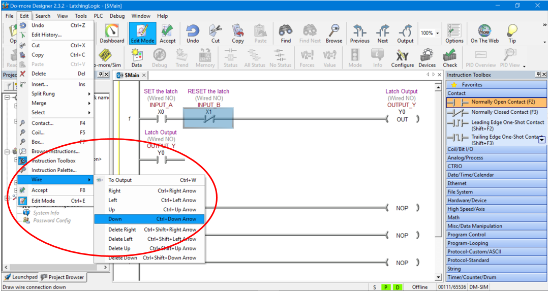
The final result should look like this….
Compile the Changes Made to the Ladder Diagram
Before we can proceed we need to compile any changes that have been made to the ladder diagram.
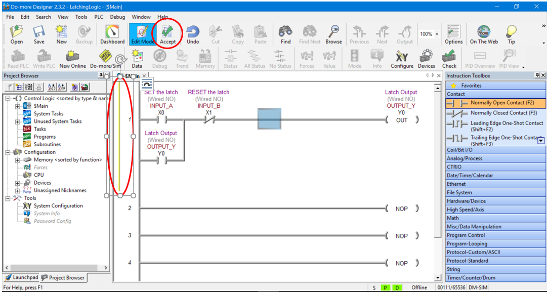
The yellow bar on the left hand side of the first rung on the ladder diagram prompts you to compile the programming changes by clicking the Accept button in the Main Toolbar….
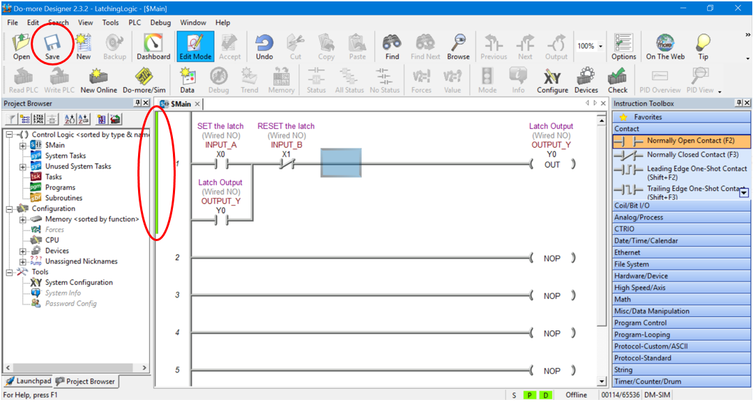
After the Accept button is clicked a green bar appears prompting you to save the ladder diagram project.
Click the Save button in the Main Toolbar and if the properties pop up box appears click ok. Once the project is saved the green bar disappears….
Connect to the PLC Simulator
We are now ready to connect to the PLC programming simulator.
The PLC programming simulator behaves just like a PLC. You need to connect to it, download your program and place it in RUN mode.
First we need to fire up the PLC simulator by clicking on the Do-more/Sim button on the Main Toolbar….
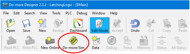
Click OK when the “Launch and Connect to Do-more PLC Simulator?” pop up appears. The Do-more PLC Simulator will then launch….
You may have some communication errors pop up. This is because we haven’t connected to the PLC simulator yet.
Please Note….The error popup box may be behind the PLC simulator window. This took a bit to figure out, very sneaky. Hope that saves you some pain!
If you get an error pop up box appear displaying “Comm Link not responding” then click Cancel….
If you get an error pop up box appear “Unable to establish a link to the PLC.” then click OK….
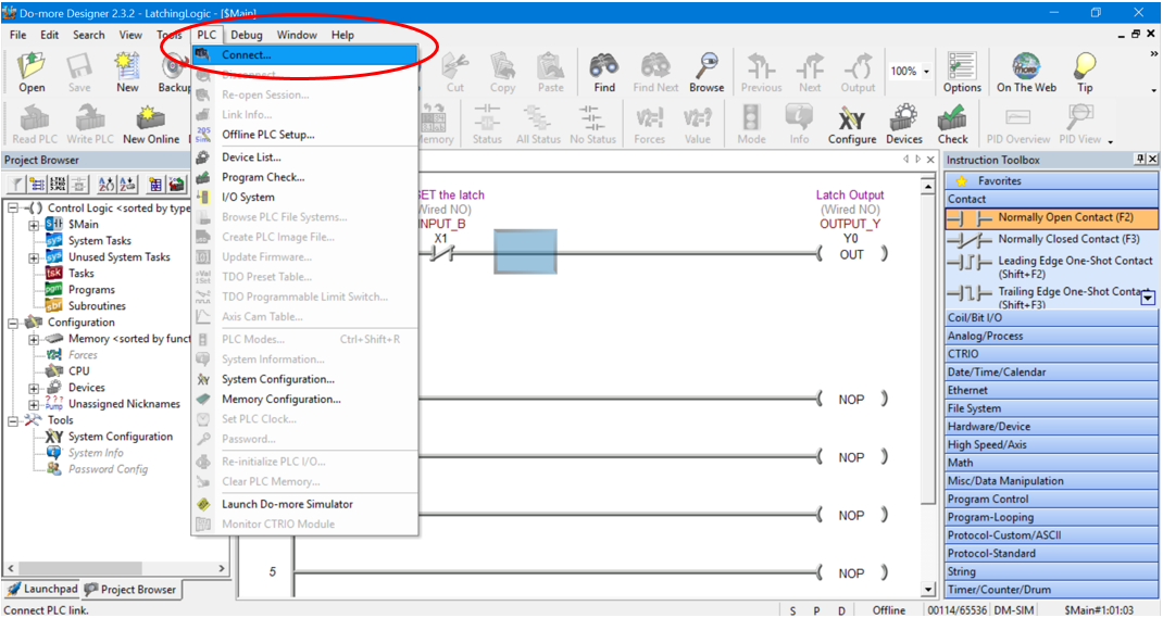
Now, let’s connect to the PLC simulator. Go to the PLC tab in the Main Toolbar and click on Connect….
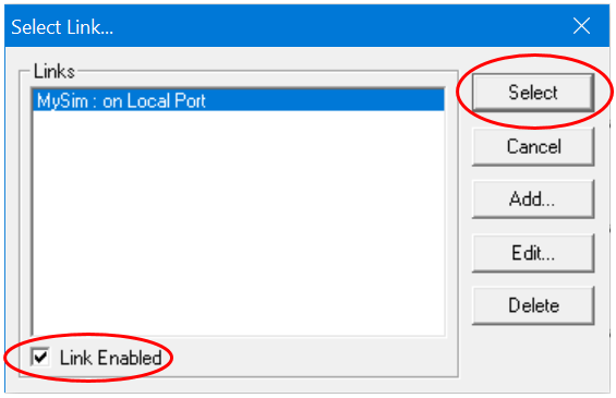
The “Select Link…” pop up box appears with “MySim: on Local Port” highlighted. Make sure to select the “Link Enabled” check box in the bottom left hand corner and then click the Select button….
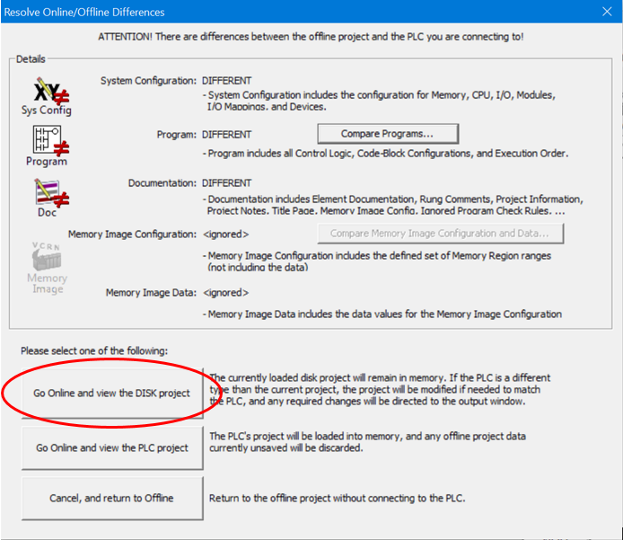
The “Resolve Online/Offline Differences” pop up box appears because we have not downloaded the ladder diagram to the PLC simulator yet. Click on “Go Online and view the DISK project” button….
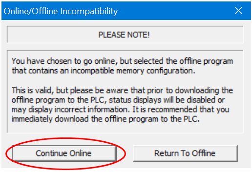
Then click the Continue Online button when the “Online/Offline Incompatibility” pop up box appears….
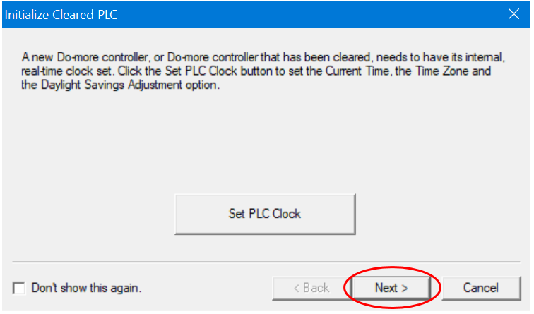
Click the Next button when the “Set PLC Clock” pop up box appears….
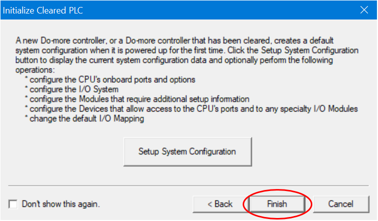
Click the Finish button when the “Setup System Configuration” pop up box appears….
We should now be connected to the PLC simulator. The Status Bar at the bottom of the ladder diagram editor should read Online….

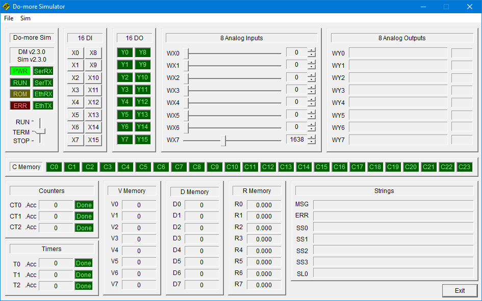
Also, the PLC simulator EthRX and EthTX indication boxes should be green to indicate simulated Ethernet transmit and receive signals between the software and PLC simulator.
If they are flashing then the Status function is turned off, we’ll take care of that a bit later….
Download and Run the PLC Simulator
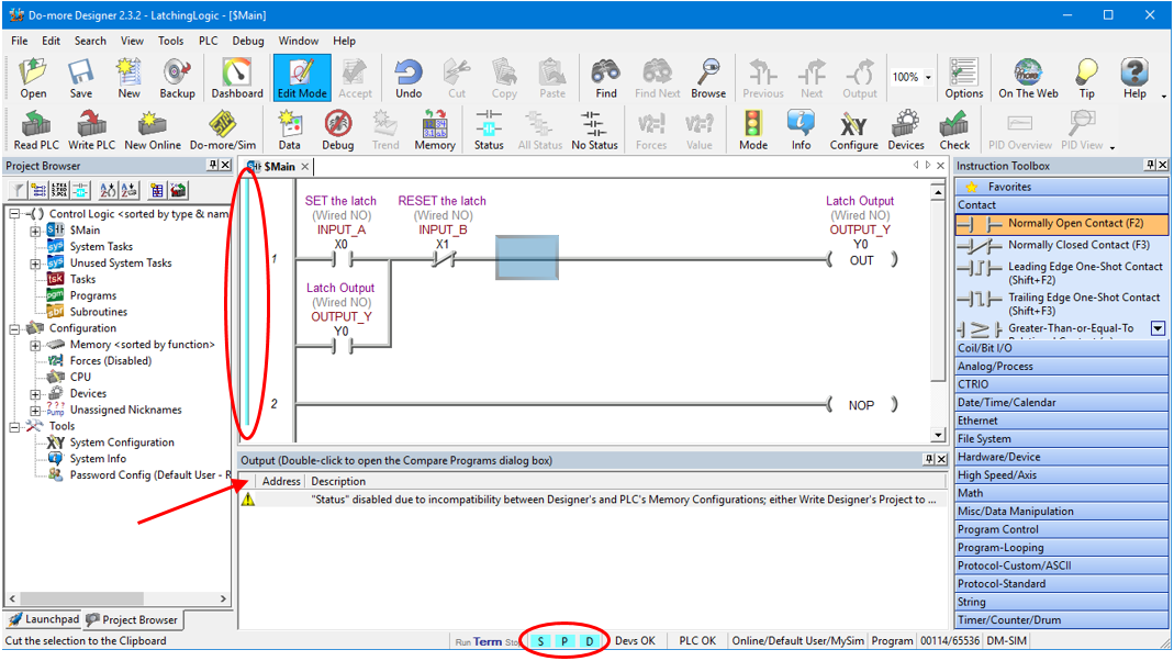
The light blue bar on the left hand side of the first rung on the ladder diagram indicate that there are differences between the offline ladder diagram and online PLC programming simulator.
Also, the S, P and D boxes in the bottom Status Bar are also highlighted light blue to indicate that there are program differences between the offline ladder diagram and online PLC programming simulator.
Lastly, there should be warning message appear just below the rung editing area which is triggered because of the differences between the offline ladder diagram and online PLC simulator …..
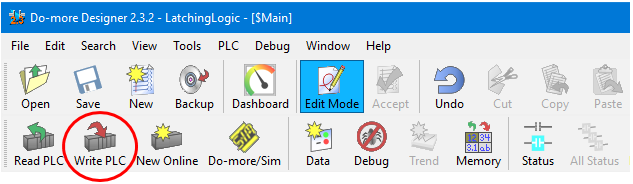
All we need to do to now is download the offline ladder diagram to the PLC programming simulator.
Click on “Write PLC” in Main Toolbar to download the ladder diagram to the PLC simulator….
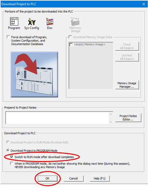
When the “Download Project to PLC” pop up box appears select the check box to “Switch to RUN mode after download completes” and then click OK….
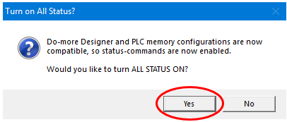
Click Yes to turn ALL STATUS ON….
Now we are connected to the PLC programming simulator, have downloaded the ladder diagram and have turned the Status indication ON.
We should have the status bar at the bottom of the ladder diagram editor window displaying Online and Run….
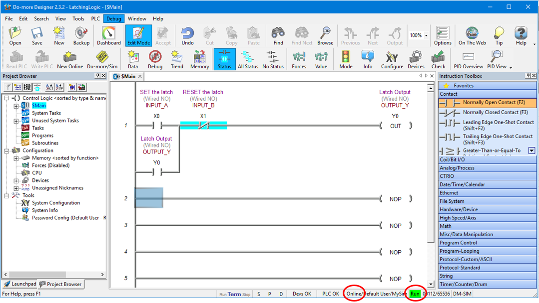
The PLC simulator EthRX and EthTX indication boxes should change to be steady green when the Status indication ON.
We have already put the PLC simulator into RUN mode when we did the download, but while we are here we can drag and drop the PLC Mode Switch from TERM to RUN….
Now we’re ready to put the PLC simulator through its paces!
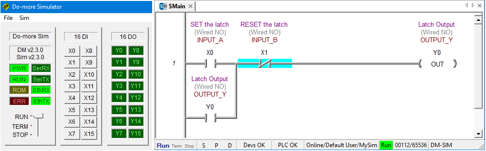
Using the PLC Simulator
To use the PLC Simulator we just need to click on the input address buttons X0-X15 to change the state of the inputs. When the button is the depressed position the input is ON and when the button is in the released position the input is OFF.
In the ladder diagram the status of the logic symbols highlights in light blue when the ladder symbol logic flow is TRUE.
If the ladder diagram symbols are not highlighting then click on “Status” in Main Toolbar to enable it….
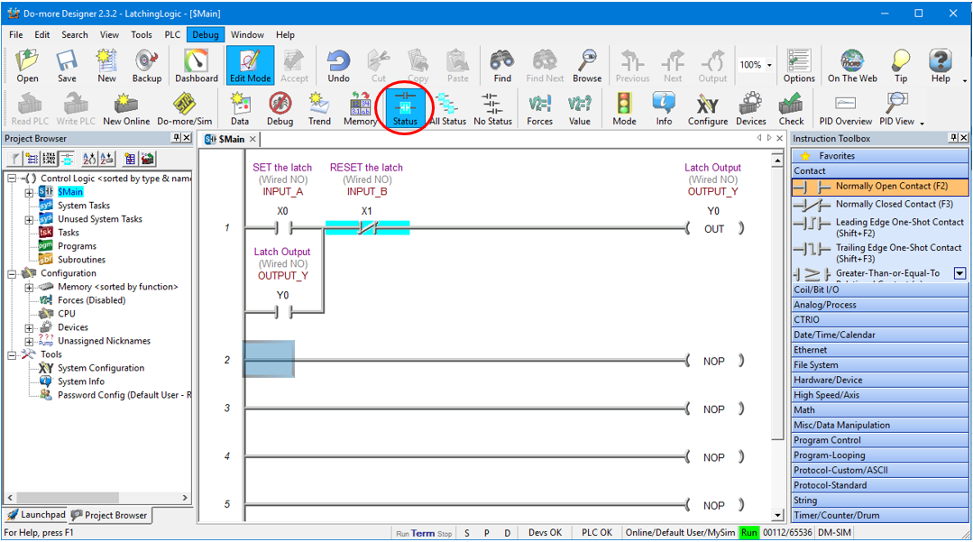
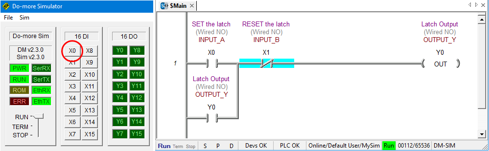
When Inputs X0 and X1 are both de-activated then the logic flow is blocked and Output Y0 is OFF….
To activate and de-activate inputs we simply click on the X0-15 buttons in the PLC simulator. One click turns the input ON another click turns it OFF….
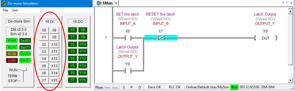
To SET the latch we must activate Input X0 and de-activated Input X1.
So, Click on the X0 button in the PLC simulator to activate Input X0. Input X1 is already de-activated so we don’t need do anything with it at this stage….
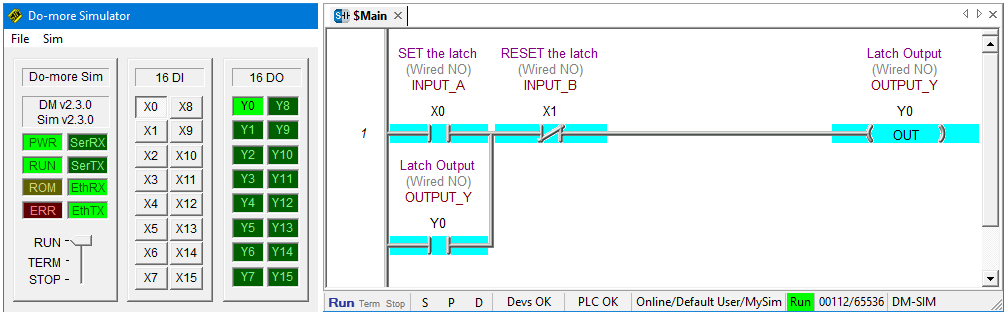
Notice that logic flows through X0 and X1 to output Y0 and they are all highlighted….
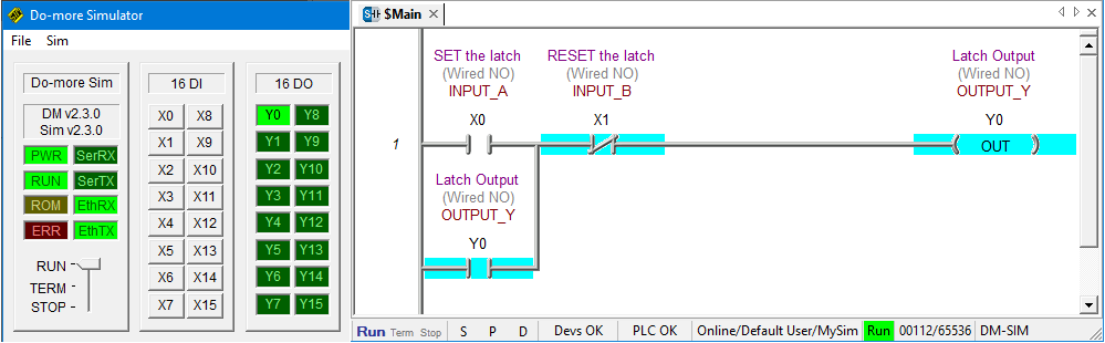
Once the latch is SET we can de-activate Input X0 by clicking on the X0 button in the PLC simulator. Notice that Output Y0 is ON and is held in….
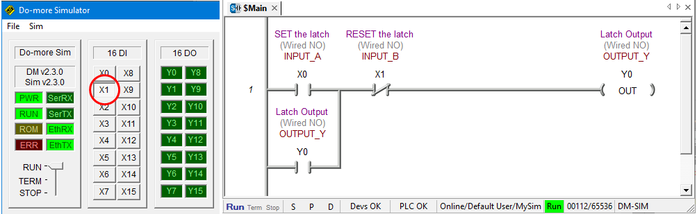
To RESET the latch activate Input X1 by clicking on the X1 button in the PLC simulator.
Because Input X1 is assigned to a normally closed contact symbol logic flow is blocked when the input is activated. That’s opposite to how a normally open contact symbol works and it’s called reverse logic….
To once again SET the latch from this point, Input X1 must be de-activated and then input X0 can be activated.
Adding a Rung Comment Using the Ladder Diagram Editor
To really start program like a pro let’s add a comment to the rung. First click on rung 1 and in the top toolbar click on Tools and then Comment Editor….
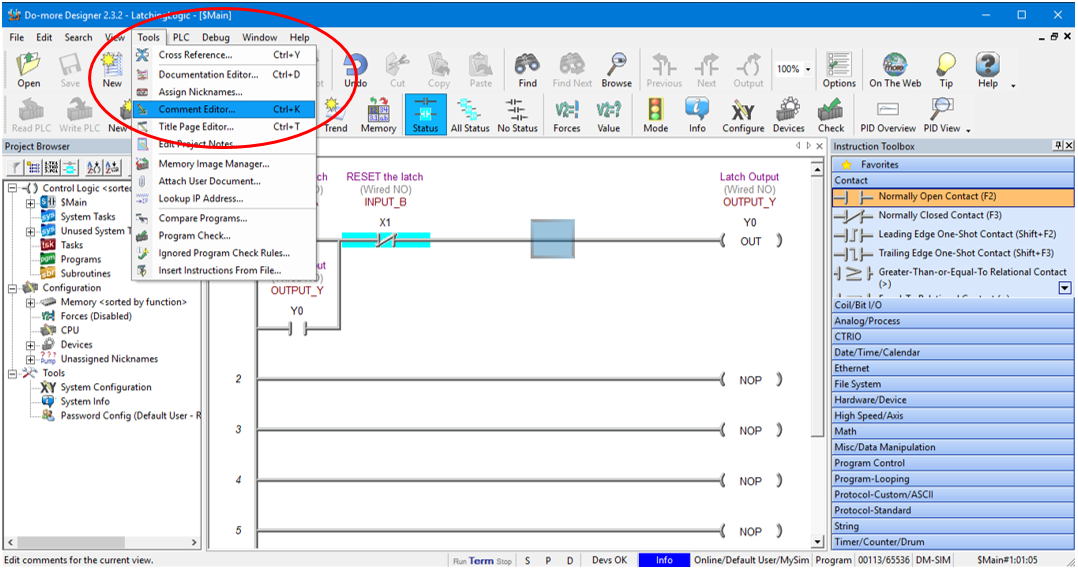
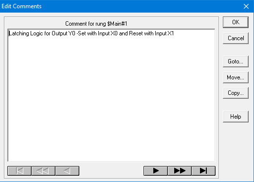
Enter the comments in the dialog box that pops up and hit OK….
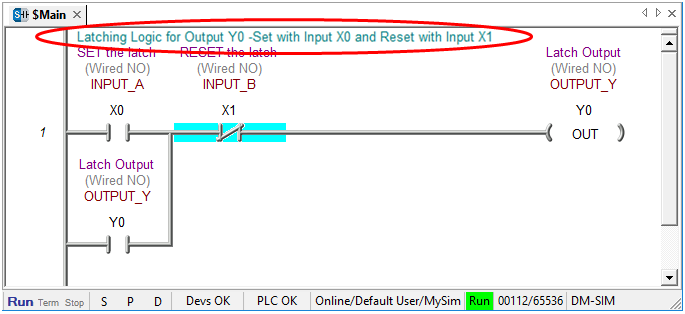
Now our ladder diagram should have the comment displayed at the very top of the rung as shown below….
Congratulations…. you have just simulated a PLC latching logic using ladder logic simulator software.
Ladder Logic Simulator Tips
Here are some handy tips to remember…
- Turn Edit Mode on in the Main Toolbar to start programming changes.
- After changing the program click Accept in the Main Toolbar to compile the program.
- Remember to save any programming changes.
- Start the PLC programming simulator before connecting to it.
- When connecting to the PLC make sure to tick the “link Enable” box.
- Put the PLC programming simulator to Terminal mode before downloading.
- To download to your ladder logic to the PLC programming simulator click on the “Write PLC” button in the Main Toolbar.
- Flick the PLC programming simulator to RUN mode to enable logic processing.
- Make sure Status is turned on in the Main Toolbar to see the logic flow indication.
If you are interested in knowing the basics of ladder logic programming then click here.