
Время на прочтение10 мин
Количество просмотров71K
Идея написать статью (которая войдет в цикл статей для новичков, остро жаждущих создавать что-то на микроконтроллерах при почти нулевых знаниях в области программирования в принципе) пришла мне после того, как мне пришлось немного отвлечься от своих основных дел, чтобы помочь другу настроить рабочую среду для написания софта под его небольшой домашний проект на основе board-а с stm32f103 на борту. Я рассчитывал, что это займет около получаса, максимум час, но ноутбук друга был на Windows 10 x64, что для меня уже непривычно (сам работаю в Ubuntu). По итогу мы потратили практически 8 часов на настройку и создание простого проекта, борясь с многими не очевидными вещами.
Параллельно с этим мне пришлось подробно объяснять, какой элемент сборки для чего нужен, а так же, как эти элементы взаимодействуют между собой, поскольку друг до этого никогда ранее с микроконтроллерами не сталкивался (от слова «видел Arduino в магазине»).
Данный материал призван помочь начинающим быстро и без проблем настроить полностью бесплатную инфраструктуру для работы с микроконтроллерами, а так же понять, каким образом происходит сборка итогового бинарного файла. Производитель и модель микроконтроллера на этапе настройки этой инфраструктуры неважны. Главное, чтобы в его основе лежало ядро ARM.
Оглавление
- Постановка задачи.
- Выбор программных средств реализации.
- Ставим Eclipse Neon 3.
- Скачиваем установщик Eclipse.
- Устанавливаем JRE.
- Устанавливаем Eclipse.
- Устанавливаем в Eclipse плагин GNU ARM Eclipse.
- Патчим JRE (на случай появления ошибки при установке плагина).
- Устанавливаем GNU ARM Eclipse Windows Build Tools.
- Скачиваем и устанавливаем GNU ARM Embedded Toolchain.
- Устанавливаем OpenOCD.
- Устанавливаем драйвера на st-link v2.
- Разбираемся, как все это работает.
- Заключение.
Постановка задачи
Требуется настроить связку таким образом, чтобы можно было:
- Скомпилировать проект, состоящий из C (C99), CPP (C++14) и ASM файлов.
- Собрать из скомпилированных файлов единый файл прошивки («.elf» и, при необходимости, «.hex», а так же «.map» файл для удобного анализа сборки).
Выбор программных средств реализации
Для решения поставленных задач нам потребуются следующие программные продукты:
- Eclipse Neon 3 для C/C++ (самая последняя версия на момент написания статьи). Будет использована нами как IDE (текстовый редактор с удобным авто дополнением + удобства по взаимодействию со средствами отладки), в которой мы будем писать код.
- JRE (на момент написания статьи, самая последняя версия 1.8.0). Без него не запустится установщик Eclipse (ну и сам Eclipse).
- GNU ARM Embedded Toolchain (на момент написания статьи, самой последней версией был 5_4-2016q3-20160926). Это комплекс нужных нам программных решений (таких как компилятор C кода «gcc», C++ кода «g++», линкер — «ld», средство загрузки и отладки финальной прошивки — «gdb» и многие другие), благодаря которым мы получим из наших файлов с исходным кодом файл с разрешением «.elf», представляющий из себя бинарный файл прошивки микроконтроллера, который в последствии будет загружен в микроконтроллер (об этом ниже).
- OpenOCD 0.10.0. С помощью него мы будем загружать наш «.elf» файл программы в микроконтроллер (на деле, OpenOCD предоставляет связь между gdb из указанного выше toolchain-а и отладчиком).
Помимо перечисленных средств, нам нужно будет поставить еще несколько небольших пакетов, о которых я скажу уже непосредственно в процессе установки.
Ставим Eclipse Neon 3
Как говорилось выше, для того, чтобы писать код, нам нужен текстовый редактор, в котором было бы удобно писать (различные методы авто-дополнения, поиска по проекту, навигация по файлам и т.д). А после того, как мы написали код, было бы неплохо, чтобы его компиляция, сборка и исполнение — были бы делом пары комбинаций клавиш (или кликов мышью, кому как удобно).
Для этих целей я использую Eclipse. Помимо редактора, он представляет еще возможность подключения различных расширений, которые значительно упрощают жизнь разработчика, сводя всю рутинную работу (сборку, компоновку, загрузку программы в контроллер) к паре кликов/нажатий.
Скачиваем установщик Eclipse
- Переходим на официальный сайт
- Справа вверху нажимаем download.
- В открывшейся окне слева выбираем download (x64/x32 должно подобраться автоматически).
- Ну и нажимаем download по центру, после чего начнется загрузка. При желании, можно про спонсировать создателей IDE…
Вот более наглядный процесс скачивания.


Устанавливаем JRE
Для того, чтобы запустить установщик, нужно сначала установить JRE. Последняя версия на момент написания статьи 1.8.0.
- Запускаем скаченный нами установщик. Получаем ошибку о том, что отсутствует JRE.
- Нажимаем «нет» и ждем перехода на сайт.
- На сайте выбираем пункт «Oracle JRE 1.8.0».
- Выбираем «Accept License Agreement».
- Скачиваем Offline версию, согласно разрядности вашей Windows.
- Запускаем скаченный файл. Дальнейшая установка проблем не вызывает.
Устанавливаем Eclipse
- Запускаем скаченный нами установщик.
- Выбираем версию для C/C++.
- Указываем путь установки (я оставил по умолчанию, и вам советую).
- Принимаем соглашение.
- Ждем окончания установки.
- Нажимаем «LAUNCH», чтобы запустить среду.
- Указываем путь, который будет использовать Eclipse для ваших проектов по умолчанию (я оставил по умолчанию), а так же ставим галочку, чтобы данное окно больше не появлялось.
- Убеждаемся, что IDE запустилась, закрываем.
- Во время закрытия можем поставить галочку, чтобы окно предупреждения о закрытии более не появлялось.
Устанавливаем в Eclipse плагин GNU ARM Eclipse
Как говорилось ранее, Eclipse позволят подключать различные плагины, упрощающие жизнь разработчика. Одним из таких плагинов является GNU ARM Eclipse. Благодаря нему мы получим возможность легко соединить все используемые нами программные компоненты при создании нового проекта под наш контроллер (как это делать, будет описано ниже).
- Переходим на официальный сайт.
- В правом столбце, под строкой «Downloads» выбираем «Plug-ins».
- Далее под строкой «The GNU ARM Eclipse plug-ins update site URL is still on SourceForge:» копируем ссылку на плагин. На момент написания статьи это была:
http://gnuarmeclipse.sourceforge.net/updates - Открываем Eclipse.
- Переходим «Help» -> «Install New Software…».
- В открывшемся окне нажимаем на «Add…».
- В еще одном открывшимся окне в пункте «Name:» пишем, например, «ARM» (название не важно), а в строку «Location:» вставляем скопированную нами с сайта ссылку.
- Нажимаем «ОК»
- Окно закроется и в списке строк появится пустой чекбокс с надписью «Pending…».
Далее в случае, если вы встретитесь с ошибкой, представленной ниже, то перейдите к пункту «Патчим JRE», а затем вернитесь и повторите всё с пункта 4.
Unable to read repository at http://gnuarmeclipse.sourceforge.net/updates/content.xml.

Unable to read repository at http://gnuarmeclipse.sourceforge.net/updates/content.xml.

Received fatal alert: handshake_failure
В случае, если ошибки не возникло или вы ее уже исправили, продолжаем дальше. - После того, как появится строка «GNU ARM C/C++ Cross Development Tools», необходимо выбрать чекбокс слева от нее и нажать «Next».
- После еще раз «Next».
- Далее принимаем лицензионное соглашение и нажимаем «Finish». Начнется процесс установки.
- В процессе установки появится предупреждение о безопасности. Жмем «ОК».
- По окончании установки потребуется перезагрузить Eclipse, для этого нажимаем «Yes» в появившемся окне.
- На этом установка этого плагина завершена.
Патчим JRE (если в пункте выше произошла ошибка)
Так уж случилось, что в JRE есть неприятный баг, мешающий нам нормально установить плагин. Не вдаваясь в природу сея явления, делаем следующие действия.
- Переходим на сайт с патчем.
- Выбираем пункт «Accept License Agreement».
- Скачиваем «.zip» архив.
- Распаковываем. В архиве 2 файла («local_policy.jar» и «US_export_policy.jar») патча и текстовый файл. Копируем эти 2 файла с разрешением «.jar» и заменяем ими файлы по адресу установленной java. В случае 64-х битной windows 10, это путь
C:\Program Files\Java\jre1.8.0_121\lib\security
Путь может быть другим в случае, если выйдет новая версия jre или у вас ОС с другой разрядностью. Главное, что вы должны зайти в папку «\lib\security» и туда скопировать с заменой эти 2 файла. На этом патч можно считать завершенным. Можно снова запустить eclipse и установить плагин.
Устанавливаем GNU ARM Eclipse Windows Build Tools
Дело в том, что в windows по умолчанию команда «make» в командной строке не работает (хотя и в linux не во всех дистрибутивах данное приложение по умолчанию установлено). Для чего нам нужно приложение «make», мы поговорим ниже, а сейчас нам просто нужно поставить плагин, который добавит возможность пользоваться им. Для этого.
- Переходим в официальный репозиторий.
- Скачиваем «.exe» файл под свою платформу. На момент написания статьи самая актуальная версия «gnuarmeclipse-build-tools-win64-2.8-201611221915-setup.exe».
- Запускаем скаченный файл и просто жмем «Next», «A Agree», «Next», «Install», «Finish».
Скачиваем и устанавливаем GNU ARM Embedded Toolchain
- Переходим на официальный сайт
- Скачиваем последнюю актуальную версию, собранную в «.exe» файл для Windows (в столбце справа).
- Запускаем скаченный файл.
- Жмем «ОК».
- Затем «Далее»
- «Принимаю»
- «Установить» (вот тут поясню, что папку можно указать любую, но лучше все-таки оставить ту, что стоит по умолчанию, во избежание проблем с регистрацией компонентов во время установки).
- По окончании установки снимаем галочку с «Показать файл ReadMe.». Остальные оставляем по умолчанию.
- «Готово»
Следующие действия несут информативный характер и могут быть пропущены. В этом случае, открывшуюся командную строку можно закрыть.
- В открывшейся командной строке пишем «cd bin», без кавычек (именно тут лежат «.exe» файлы всех компонентов toolchain-а).
- Набираем «arm-none-eabi-gcc —version», без кавычек.
- Убедившись, что gcc ответил, закрываем консоль.
Устанавливаем OpenOCD
Со средой и toolchain-ом разобрались. Далее нужно установить OpenOCD, с помощью которого Eclipse через arm-none-eabi-gdb будет рулить контроллером. Тут все просто.
- Переходим в официальный репозиторий.
- Скачиваем «.exe» файл под свою ОС. На момент написания статьи, самая актуальная версия «gnuarmeclipse-openocd-win64-0.10.0-201701241841-setup.exe».
- Запускаем скаченный «.exe». Установку производим не меняя ничего (в том числе и путь).
Устанавливаем драйвера на st-link v2
OpenOCD управляет контроллером, это верно, но для этого ему требуется драйвер на отладчик. В нашем случае, это st-link v2. В случае, если у вас другой отладчик, то эту часть можно пропустить.
Вне зависимости от того, поддельный у вас st-link или оригинальный, драйвера одни и те же. Начнем.
- Переходим на официальную страницу st-link v2
- Внизу страницы скачиваем файл «STSW-LINK009» с описанием «ST-LINK, ST-LINK/V2, ST-LINK/V2-1 USB driver signed for Windows7, Windows8, Windows10».
- При переходе на другую страницу нажимаем «Download» в нижней части страницы. Тут важно заметить, что если вы сидите в интернете не через VPN, то вам придется зарегистрироваться. Как это делать, я описывать не буду. После чего файл будет скачен.
- Разархивировав архив выбираем файл установки драйвера согласно разрядности ОС. В моем случае, это «dpinst_amd64.exe».
- Во время установки соглашаемся со всеми требованиями. И выбираем чекбокс «Всегда доверять программному обеспечению STMicroelectronics».
Разбираемся, как все это работает
Вот мы установили все необходимые компоненты, создали проект в Eclipse (о том, как создать и настроить проект, будет написано в следующей статье) и нажали «Ctrl+B». Получили готовый файл прошивки, который нажатием по иконке «отладка» можно загрузить в контроллер и начать непосредственно отладку. Но что скрывается за всеми этими действиями? А происходит следующее:
- После того, как вы нажимаете «Ctrl+B» — Eclipse анализирует дерево каталогов проекта (все созданные нами папки и файлы, находящиеся в них). Для этого он пользуется путями к файлам, которые мы укажем при создании проекта.
- После этого Eclipse создает makefile. Этот файл содержит в себе указания для программы make о том, какие файлы нужно компилировать (которые мы добавили в проект, указав при этом путь к каталогам, где они лежат), с какими параметрами (здесь Eclipse пользуется заполненными нами параметрами во вкладке «C/C++ Build») и как компоновать в итоговом файле прошивки скомпилированные ранее файлы.
Заметка: makefile не имеет расширения. - Далее Eclipse вызывает программу make с указанием пути к созданному makefile, а так же параметры сборки, указанные нами при настройке проекта (это, например количество потоков процессора, используемого для компиляции).
- Программа make проходит по всем файлам проекта, согласно указаниям в makefile-е и получает для каждого файла файл с расширением «.o». Эти файлы располагаются в папке Debug точно так же, как и в основном проекта (с сохранением иерархии дерева). Если в каком-то файле будет ошибка, вы получите уведомление об этом, выделенное красным в консоли компиляции (по умолчанию она располагается внизу экрана). При возникновении ошибки компиляции, дальнейшая компиляция и сборка прекращаются. Для компиляции файлов make использует указанный в makefile toolchain (вернее сказать, его компоненты: gcc/g++). Путь к toolchain-у Eclipse берет, опять же, из настроек проекта.
- После создания всех «.o» файлов из «.c», «.cpp», «.S» (прошу заметить, файлы с ассемблерным кодом обязательно должны иметь расширение большой буквы «S», иначе при создании makefile данные файлы будут просто проигнорированы, что ведет к трудно уловимым ошибкам) make вызывает компоновщик (arm-none-eabi-ld из установленного нами toolchain-а) с указанием путей к файлам компоновки из проекта (файлы с расширением «.ld», которые мы добавим в проект). Тут компоновщик, опираясь на указанные в файлах компоновки с расширением «.ld» указания (правила) пытается собрать из кучи «.o» файлов один объектный файл с разрешением «.elf» (и, если есть такие указания в makefile, «.hex» и «.map»). Важно заметить, именно linker (компоновщик) решает, какие куски кода и данных можно выкинуть из программы (если сочтет, что они нигде не используются и просто занимают место). Таким образом, если мы создадим 1000 глобальных переменных, из которых будем использовать в коде только 2, то остальные (если явно не задано, что их нельзя исключать из проекта ключевым словом «volatile» или указанием «положить в секцию, из которой ничего нельзя убирать») будут исключены из конечного объектного файла, что даст нам больше свободной памяти.
- После того, как мы получили конечный объектный файл, мы можем его «зашить» в контроллер и провести отладку. Для этого Eclipse вызывает программу OpenOCD с указанием пути к файлу «openocd.cfg» (имя может быть любое, с расширением «.cfg», но в случае, если вам придется когда-нибудь отлаживаться из командной строки, а не из под IDE, то вы ощутите, что правильно названный файл для OpenOCD позволяет вам не писать имя файла конфигурации (т.к. в случае, если файл конфигурации был не указан, то автоматически ищется файл с таким именем)).
В случае, если указанный файл существует, OpenOCD, согласно параметрам в файле, попытается соединиться с микроконтроллером. В случае, если подключение верно, вы получим уведомление о том, что связь установлена, отладчик контроллера работает.
Для того, чтобы связаться с контроллером, OpenOCD использует драйвер для st-link-а, установленный нами в начале. - После того, как OpenOCD смог установить связь с контроллером, он открывает telnet соединение. Если не вдаваться в подробности, это нужно для того, чтобы arm-none-eabi-gdb мог успешно управлять контроллером.
- После того, как telnet соединение установлено, Eclipse запускает arm-none-eabi-gdb с указанием порта, к которому нужно подключиться (тот, что открыл OpenOCD).
- Далее Eclipse посылает в gdb команды инициализации (стереть flash, записать файл прошивки, установить точку остановки на main, и еще несколько нобязательных параметров).
- После этого в Eclipse мы видим указатель на первую строку кода в файле main и можем начать отладку.
Чисто технически, все проделанные тут операции можно делать каждый раз вручную, но, согласитесь, куда удобнее просто нажать на клавишу и наслаждаться запущенной отладкой.
Заключение
В этой статье я постарался подробно описать процесс конфигурации сборки под Windows. В случае, если у вас появятся вопросы — пишите в личку, постараюсь помочь и добавить в статью проблему + ее решение.
В следующей статье я расскажу, как настроить Eclipse под конкретный контроллер, собрать демонстрационный проект и настроить отладку.
Debugging the STM32F103 with an ST LINK/V2 and OpenOCD
Published 10/3/2017
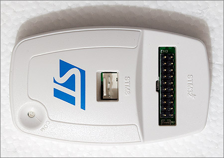
Debugging is a very useful tool when working with Microcontrollers. I decided to order an ST-Link/V2, which is available for a few Euros (I paid roughly 6 EUR for mine). This device supports the SWD protocol for STM32 chips, which allows the chip to be programmed and debugged from 4 pins.
The first step is to connect the 4 pins. In the following picture, red is the target device voltage, grey is GND, green is IO and blue is CLK. Note that the device still needs external power, which I supply via the micro USB cable (not shown).
OpenOCD is an open source on chip debugger which can be downloaded from http://openocd.org/. It takes a client server approach, and the first step is to start the daemon which connects to the target device. This can be done using the following command, where -s tells openocd where to search for scripts and we tell it to use the stlink-v2 config as well as the stm32f1x config.
.\openocd.exe -s ..\scripts\ -f interface\stlink-v2.cfg -f target\stm32f1x.cfg
Once the OpenOCD daemon is started, we need to use telnet to connect to the device. For this we can connect to the local machine on port 4444, and can directly start issuing commands to the device.
telnet localhost 4444
With OpenOCD connected we can start using various commands. The first thing we can do is reset the device and tell it to break on the first command. This can be done by calling «reset halt» as follows:
> reset halttarget halted due to debug-request, current mode: ThreadxPSR: 0x01000000 pc: 0x00000152 msp: 0x20005000
As can be seen, our program counter (pc) is at 0x152, so if we want to see the assembler at that point, we can ask OpenOCD to disassemble it for us, using the arm disassemble command, giving it the address as well as the number of instructions to disassemble.
> arm disassemble 0x152 200x00000152 0xe92d4ff0 PUSH.W {r4, r5, r6, r7, r8, r9, r10, r11, r14}0x00000156 0xb083 SUB SP, #0xc0x00000158 0xf2400004 MOVW r0, #4 ; 0x0040x0000015c 0xf2400108 MOVW r1, #8 ; 0x0080x00000160 0xf2c20000 MOVT r0, #8192 ; 0x20000x00000164 0xf2c20100 MOVT r1, #8192 ; 0x20000x00000168 0x1a09 SUBS r1, r1, r00x0000016a 0x2901 CMP r1, #0x010x0000016c 0xbfa8 IT GE0x0000016e 0xf000fb1c BL 0x000007aa0x00000172 0xf2400000 MOVW r0, #0 ; 0000x00000176 0xf2400104 MOVW r1, #4 ; 0x0040x0000017a 0xf2c20000 MOVT r0, #8192 ; 0x20000x0000017e 0xf2c20100 MOVT r1, #8192 ; 0x20000x00000182 0x1a0a SUBS r2, r1, r00x00000184 0x2a01 CMP r2, #0x010x00000186 0xdb05 BLT 0x000001940x00000188 0xf24071f8 MOVW r1, #2040 ; 0x7f80x0000018c 0xf2c00100 MOVT r1, #0 ; 00000x00000190 0xf000fb00 BL 0x00000794
We can also use the debugger to dump raw memory, using the mdb command, we tell it where and how much memory to dump:
> mdb 0x0 640x00000000: 00 50 00 20 53 01 00 00 51 01 00 00 51 01 00 00 51 01 00 00 51 01 00 00 51 01 00 00 00 00 00 000x00000020: 51 01 00 00 51 01 00 00 00 00 00 00 51 01 00 00 51 01 00 00 51 01 00 00 51 01 00 00 51 01 00 00
Setting breakpoints can be done using the bp commands, and they can be removed using the rbp command, as in the following examples:
> bp 0x7aa 2breakpoint set at 0x000007aa> rbp 0x7aa
Otherwise there is the resume command, to continue execution in halted state, as well as the step command, to only execute a single opcode.
Another nice command is the reg command, which dumps all registers:
> reg===== arm v7m registers(0) r0 (/32): 0x20000004(1) r1 (/32): 0x00000004(2) r2 (/32): 0xD4F014C0(3) r3 (/32): 0x04A82F37(4) r4 (/32): 0x20000004(5) r5 (/32): 0xFFCFFEDD(6) r6 (/32): 0x0C06C5A6(7) r7 (/32): 0x390A2280(8) r8 (/32): 0x9A9F8FD8(9) r9 (/32): 0xFFDF5B9D(10) r10 (/32): 0xD4368C54(11) r11 (/32): 0x680C1352(12) r12 (/32): 0x7DBEF177(13) sp (/32): 0x20005000(14) lr (/32): 0xFFFFFFFF(15) pc (/32): 0x00000152(16) xPSR (/32): 0x01000000(17) msp (/32): 0x20005000(18) psp (/32): 0xC4E16220(19) primask (/1): 0x00(20) basepri (/8): 0x00(21) faultmask (/1): 0x00(22) control (/2): 0x00===== Cortex-M DWT register(23) dwt_ctrl (/32)(24) dwt_cyccnt (/32)(25) dwt_0_comp (/32)(26) dwt_0_mask (/4)(27) dwt_0_function (/32)(28) dwt_1_comp (/32)(29) dwt_1_mask (/4)(30) dwt_1_function (/32)(31) dwt_2_comp (/32)(32) dwt_2_mask (/4)(33) dwt_2_function (/32)(34) dwt_3_comp (/32)(35) dwt_3_mask (/4)(36) dwt_3_function (/32)
The problem I was facing in http://localhost:8089/Home/6-rust-stm-handling-static-variables with my rust code crashing, seems to be that the code produces the following code for the memory initialization routine:
> arm disassemble 0x7aa 200x000007aa 0xb510 PUSH {r4, r14}0x000007ac 0x4604 MOV r4, r00x000007ae 0x2901 CMP r1, #0x010x000007b0 0xbfa4 ITE GE0x000007b2 0x4620 MOV r0, r40x000007b4 0xf7fffff9 BL 0x000007aa
This code essentially ends up in an infinite loop, because the r1 register is never changed. Each time it loops it jumps to 0x7aa, which contains a push command causing the stack pointer to decrease. This continues untill the microcontroller overwrites memory which it is not allowed to write, causing it to land in a fault interrupt. I’m still not entirely sure why the compiler produces this code however.
This can be confirmed by running and then halting the microcontroller:
> resume> halttarget halted due to debug-request, current mode: Handler HardFaultxPSR: 0x21000003 pc: 0x00000150 msp: 0x1fffffe0
- Docs
- Support
- Blog
- Projects
- Store
- Console
- IDE
Posted on Sep 9, 2014 in stm32
Over the last few years I’ve amassed quite a collection of STM32 development boards. Third party boards dominate my collection for the F1 series whilst I have official ST discovery boards for the F0, F4 and F1 Value Line. We’ve been lucky with the official ST discovery boards because they all come with an ST-Link included on the PCB so you don’t need to buy anything else at all to get a complete C++ development and visual debugging environment up and running.
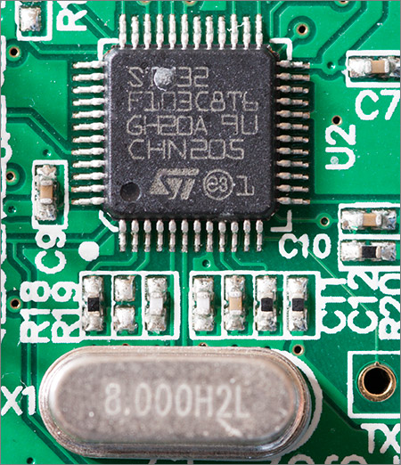
The embedded ST-Link debugger on the discovery boards is implemented inside ST’s own STMF32F103C8T6 MCU in a 48 pin QFP package with an external 8MHz clock. I suppose that when you are the manufacturer of these MCUs it’s cheaper to do it this way than to manufacture a custom ST-Link IC just for this purpose
The situation with the commonly available third party F1 boards was always less clear because up until a year or so ago the ST-Link interface was not fully operational in the popular and free OpenOCD debugger. Because of the lack of support in OpenOCD for ST-Link v2 I was forced to go down the third party route and use the Olimex ARM-USB-TINY-H for all my F1 programming and debugging.
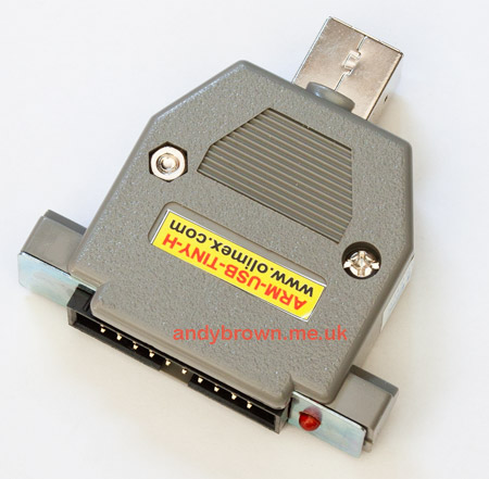
This is a JTAG-based programmer that is compatible with ARM devices from many manufacturers. It’s fast, reliable and it costs double what you should be paying for an ST-Link v2.
Times have changed since those early days and now since the release of version 0.7.0 of OpenOCD the support for ST-Link is completely stable and there’s no reason why you can’t use ST-Link v2 for all your STM32 programming and debugging needs.
Not only is it the most compatible of all the programmers and debuggers, it’s also probably the cheapest. At the time of writing it’s only £18.68 plus VAT at Farnell. If you’re buying elsewhere then make sure that you’re getting the ‘v2’ device. There are still some places offering the older ‘v1’ version.
In the rest of this article I’ll take each board that I’ve got and explain how to connect and use it with OpenOCD using the ST-Link v2 programmer. Once you’ve got a live OpenOCD connection you can flash your .hex binaries and do interactive debugging using Eclipse.
The version of OpenOCD that I’ll be using is 0.8.0 and my test system will be Windows 7 x64 using Cygwin. The OpenOCD binaries were downloaded from Freddie Chopin’s site.
If you’re installing OpenOCD for the first time on Windows then you’re likely to run into an issue with the libusb package that shows up as the following error:
Open On-Chip Debugger 0.8.0 (2014-04-28-08:42)
Licensed under GNU GPL v2
For bug reports, read
        http://openocd.sourceforge.net/doc/doxygen/bugs.html
srst_only separate srst_nogate srst_open_drain connect_deassert_srst
Info : This adapter doesn't support configurable speed
Error: libusb_open() failed with LIBUSB_ERROR_NOT_SUPPORTED
Error: open failed
in procedure 'transport'
in procedure 'init'
To resolve this, download and run the zadig utility. Zadig automates the process of connecting libusb to one of the supported USB drivers. It’s as simple as a single click.
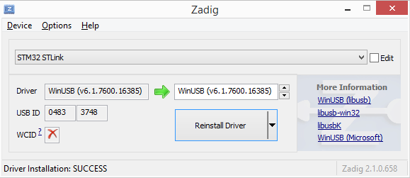
Once zadig has done its work you can run OpenOCD again and it’ll work this time.
STM32F103VET6 ‘Mini’ board
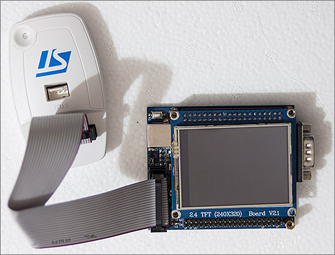
This was the first F1 development board that I bought some years ago and it’s still available in various forms on ebay. Connectivity with the ST-Link device is via a direct connection to the 20-pin JTAG/SWD header using the supplied cable. Since the ST-Link connection is not designed to supply power to the target board you must also connect up the USB A-B cable.
Here’s the command sequence for connecting with OpenOCD:
$ pwd
/cygdrive/p/docs/cyghome/andy/openocd-0.8.0
$ bin-x64/openocd-x64-0.8.0.exe -f scripts/interface/stlink-v2.cfg -f scripts/target/stm32f1x_stlink.cfg
Open On-Chip Debugger 0.8.0 (2014-04-28-08:42)
Licensed under GNU GPL v2
For bug reports, read
        http://openocd.sourceforge.net/doc/doxygen/bugs.html
Info : This adapter doesn't support configurable speed
Info : STLINK v2 JTAG v17 API v2 SWIM v4 VID 0x0483 PID 0x3748
Info : using stlink api v2
Info : Target voltage: 3.225049
Info : stm32f1x.cpu: hardware has 6 breakpoints, 4 watchpoints
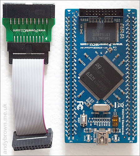
‘Redbull’ STM32F103ZET6 board
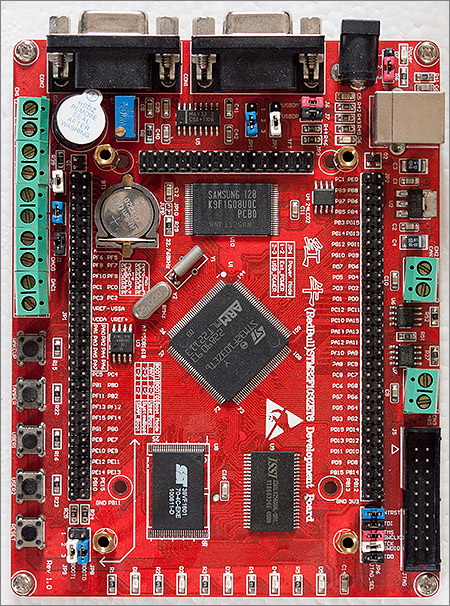
This is my favourite F1 development board. It’s based around the full fat STM32F103ZET6 144-pin MCU and comes with additional SRAM and flash resources as well as the usual buttons and LEDs. On my board the additional SRAM and flash ICs are the ISSI IS61LV256160AL-10TL, the SST 39VF1601 and the Samsung K9F1G08U0C. These are correctly mapped to the MCU’s FSMC peripheral as you’d expect. My only minor gripe with the board is that there’s not enough exposed GND and 3.3V pins for hassle-free connecting of external peripherals.
Connecting the board with ST-Link is identical to the ‘Mini’ board described above. Simply connect it up to the 20-pin JTAG header and run the same command sequence:
$ pwd
/cygdrive/p/docs/cyghome/andy/openocd-0.8.0
$ bin-x64/openocd-x64-0.8.0.exe -f scripts/interface/stlink-v2.cfg -f scripts/target/stm32f1x_stlink.cfg
Open On-Chip Debugger 0.8.0 (2014-04-28-08:42)
Licensed under GNU GPL v2
For bug reports, read
        http://openocd.sourceforge.net/doc/doxygen/bugs.html
Info : This adapter doesn't support configurable speed
Info : STLINK v2 JTAG v17 API v2 SWIM v4 VID 0x0483 PID 0x3748
Info : using stlink api v2
Info : Target voltage: 3.272160
Info : stm32f1x.cpu: hardware has 6 breakpoints, 4 watchpoints
PowerMCU STMF407ZGT6 board
Making an entry into the F4 development board business can’t be easy when ST sell the discovery board for such a low price. Therefore any competitor is going to have to offer significant extras to have any hope of selling their board.
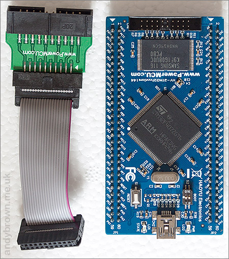
This development board offers several nice upgrades to ST’s discovery offering. Firstly the MCU is the 144-pin device which means that all banks of the FSMC peripheral are available and this board builds on that by including a Samsung K9F1G08U0C NAND flash chip on the front side of the board.
Note that the external clock is 25MHz which means that a straight recompile of firmware that targets the discovery board will not be enough. You will need to go into the startup code and set the appropriate PLL multipliers to get the clock tree set up correctly. ST provide an Excel spreadsheet with macros that will do this for you – search for AN3988 to get it.
I can’t finish up with the front side of this board without having a moan about the JTAG/SWD header. It’s a reduced size 2mm pitch socket that requires an adaptor to connect to the standard 2.54mm JTAG header. I can’t seriously believe that it was cheaper to save a few millimeters of board space than it was to ship a cable adaptor with every board as they do. Barmy decision.
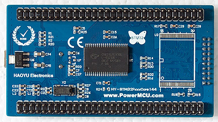
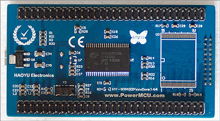
I need to show the back of the board because there’s a few significant components down there. The large IC is a Cypress CY62157EV30L SRAM device, correctly connected to the MCUs FSMC peripheral. The unpopulated footprint looks like it was originally designed to hold a NOR flash IC but is unpopulated on my board.
I’m pleased to see the linear regulator is an AMS1117 3.3V device. This a much more heavy duty regulator than the one on the discovery board and will allow you to connect more demanding peripherals than you can attach to the discovery board.
And so on to the OpenOCD connectivity. Hook up your standard JTAG cable to the board via the adaptor supplied with the board and here’s how to attach to it:
$ pwd
/cygdrive/p/docs/cyghome/andy/openocd-0.8.0
$ bin-x64/openocd-x64-0.8.0.exe -f scripts/interface/stlink-v2.cfg -f scripts/target/stm32f4x_stlink.cfg
Open On-Chip Debugger 0.8.0 (2014-04-28-08:42)
Licensed under GNU GPL v2
For bug reports, read
        http://openocd.sourceforge.net/doc/doxygen/bugs.html
Info : This adapter doesn't support configurable speed
Info : STLINK v2 JTAG v17 API v2 SWIM v4 VID 0x0483 PID 0x3748
Info : using stlink api v2
Info : Target voltage: 3.217755
Info : stm32f4x.cpu: hardware has 6 breakpoints, 4 watchpoints
PowerMCU STMF207ZGT6 board
This entry into the F2 development board market is from PowerMCU.com and it’s pretty much identical to the F4 board that I described above, including the external 25MHz crystal that will require some attention in your code if you’re already working with something that assumes an 8MHz crystal.
All the additional features on this board are identical to those on their F4 offering so I won’t repeat them here.
The back side of the board yields no surprises having already seen the F4 board. Let’s move quickly on to the OpenOCD commands to connect to it:
/cygdrive/p/docs/cyghome/andy/openocd-0.8.0
$ bin-x64/openocd-x64-0.8.0.exe -f scripts/interface/stlink-v2.cfg -f scripts/target/stm32f2x_stlink.cfg
Open On-Chip Debugger 0.8.0 (2014-04-28-08:42)
Licensed under GNU GPL v2
For bug reports, read
        http://openocd.sourceforge.net/doc/doxygen/bugs.html
Info : This adapter doesn't support configurable speed
Info : STLINK v2 JTAG v17 API v2 SWIM v4 VID 0x0483 PID 0x3748
Info : using stlink api v2
Info : Target voltage: 3.238120
Info : stm32f2x.cpu: hardware has 6 breakpoints, 4 watchpoints
Cheap ST-Link clones
Recently there have been a number of bare boards appearing on ebay for as little as £5.00 that claim to function as ST-Link v2 devices. They’re so cheap that I thought I’d pick one up and see what the story is.
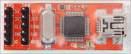
My first observation is that I can’t see how these things are legal at all. Apart from the obvious unauthorised use of the USB VID and PID that belong to ST Microelectronics there is the question of the firmware implementation itself. If you look closely at an official ST discovery board then you’ll see that ST-Link is implemented in firmware inside an STM32F103 device. The exact same model of STM32F103 appears on this clone. I can only surmise that the manufacturer has somehow managed to circumvent ST’s code readout protection (assuming that ST remembered to enable that protection) and cloned the firmware byte for byte.
Does it work though? Let’s try it out and see. I’m going to refer to it as the FakeLink from here on just so you know that’s the one I’m using. I hooked it up to the ‘RedBull’ F1 board using jumper wires connected from the FakeLink to the JTAG socket using the following pinout. GND -> GND(4), 3V3 -> board 3V3, CLK -> SWCLK(9) and IO -> SWDIO(7).
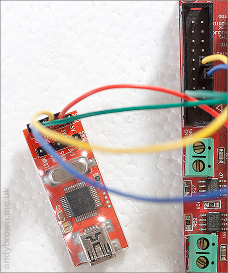
For the tests I connected just the FakeLink USB connector to the computer. It seems that the FakeLink can power the dev board from its 3.3V output. I also tested it with the dev board receiving power from its USB connector and the results were the same.
Now let’s pretend it’s a real ST-Link and connect to it via OpenOCD.
$ bin-x64/openocd-x64-0.8.0.exe -f scripts/interface/stlink-v2.cfg -f scripts/target/stm32f1x_stlink.cfg
Open On-Chip Debugger 0.8.0 (2014-04-28-08:42)
Licensed under GNU GPL v2
For bug reports, read
        http://openocd.sourceforge.net/doc/doxygen/bugs.html
Info : This adapter doesn't support configurable speed
Info : STLINK v2 JTAG v17 API v2 SWIM v4 VID 0x0483 PID 0x3748
Info : using stlink api v2
Info : Target voltage: 3.560727
Info : stm32f1x.cpu: hardware has 6 breakpoints, 4 watchpoints
So far so good though the target voltage is higher than I would have expected. Next I’ll try the basic functionality and flash a ‘blink’ example to the MCU using telnet to control the connected OpenOCD server.
$ telnet localhost 4444
Trying 127.0.0.1...
Connected to localhost.
Escape character is '^]'.
Open On-Chip Debugger
> reset init
target state: halted
target halted due to debug-request, current mode: Thread
xPSR: 0x01000000 pc: 0x08000238 msp: 0x2000fffc
> flash write_image erase p:/tmp/blink.hex
auto erase enabled
target state: halted
target halted due to breakpoint, current mode: Thread
xPSR: 0x61000000 pc: 0x2000003a msp: 0x2000fffc
wrote 8192 bytes from file p:/tmp/blink.hex in 0.771045s (10.376 KiB/s)
> reset
The first command, reset init resets the MCU and brings it under the control of OpenOCD. The next command, flash write_image erase p:/tmp/blink.hex writes the compiled blink program to the MCU and finally we reset it to run the program with reset.
It worked as expected. So far so good for the FakeLink. Now for the only test that really matters, can I debug the program from Eclipse just like I can with the real ST-Link? People often write to me asking for the Eclipse debug settings that I use, so here they are:
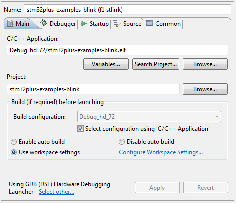
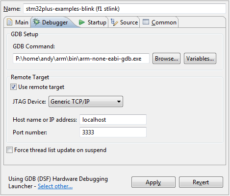
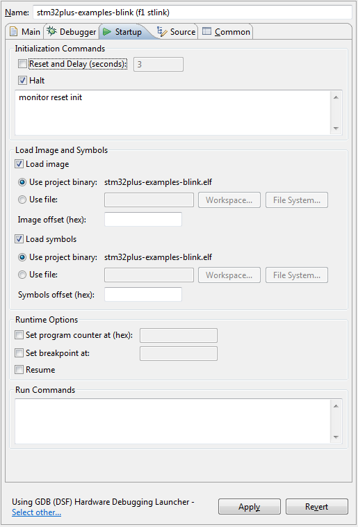
Executing the debug configuration resulted in everything working just as I would expect it to. Eclipse was able to auto-flash the compiled executable and then set breakpoints and single step through the code. Basically it just worked.
Verdict on the fake ST-Link
Functionally the device passed every test that I executed so in that respect I have to give it a plus mark. However, I just can’t condone the blatant illegality of the thing. It is an unashamed rip-off of ST’s intellectual property as well as the PID/VID owned by ST. In my view, especially as the offical ST-Link not expensive, the right thing to do is to buy the ST device and don’t support these clones.
While working on my OpenDPS Project
I needed to use OpenOCD onw Windows. I cheated and used the one that came with VisualGDB running in a DOS Window:
from the \openocd\scripts directory:
C:\Users\gojimmypi\AppData\Local\VisualGDB\EmbeddedDebugPackages\com.sysprogs.arm.openocd\bin\openocd -f interface/stlink-v2.cfg -f target/stm32f1x.cfg
but really, I want to have OpenOCD in Ubuntu.
So I downloaded it from
https://launchpad.net/ubuntu/+source/openocd
or specifically:
wget
https://launchpad.net/ubuntu/+archive/primary/+files/openocd_0.9.0.orig.tar.gz
and unzipped it:
tar -xzvf openocd_0.9.0.orig.tar.gz
There’s an INSTALL file that gives basic instructions:
./configure
make
sudo make install
if you don’t use «sudo» on that last command, you’ll get this wonderfully intuitive error:
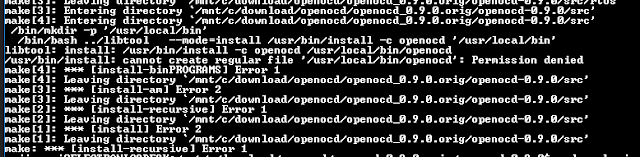
(ho — and people wonder why Windows is so popular.. but I digress…)
Now from the /openocd/scripts directory, this command:
openocd -f interface/stlink-v2.cfg -f target/stm32f1x.cfg
or simply:
from the /openocd directory.
well, it does not find my ST-LINK, or any other USB devices. It seems WSL does not recognize any of my USB ports.
$ lsusb
unable to initialize libusb: -99
On to installing the toolchain in a Debian VM….
If there are problems, well there’s
https://answers.launchpad.net/ubuntu/
https://github.com/Microsoft/BashOnWindows/issues/
Copyright (c) gojimmypi all rights reserved. Blogger Image Move Cleaned: 5/3/2021 1:35:52 PM