
Summary
Standards: RFC 2661
L2TP is a secure tunnel protocol for transporting IP traffic using PPP. L2TP encapsulates PPP in virtual lines that run over IP, Frame Relay and other protocols (that are not currently supported by MikroTik RouterOS). L2TP incorporates PPP and MPPE (Microsoft Point to Point Encryption) to make encrypted links. The purpose of this protocol is to allow the Layer 2 and PPP endpoints to reside on different devices interconnected by a packet-switched network. With L2TP, a user has a Layer 2 connection to an access concentrator — LAC (e.g., modem bank, ADSL DSLAM, etc.), and the concentrator then tunnels individual PPP frames to the Network Access Server — NAS. This allows the actual processing of PPP packets to be separated from the termination of the Layer 2 circuit. From the user’s perspective, there is no functional difference between having the L2 circuit terminate in a NAS directly or using L2TP.
It may also be useful to use L2TP just as any other tunneling protocol with or without encryption. The L2TP standard says that the most secure way to encrypt data is using L2TP over IPsec (Note that it is default mode for Microsoft L2TP client) as all L2TP control and data packets for a particular tunnel appear as homogeneous UDP/IP data packets to the IPsec system.
Multilink PPP (MP) is supported in order to provide MRRU (the ability to transmit full-sized 1500 and larger packets) and bridging over PPP links (using Bridge Control Protocol (BCP) that allows to send raw Ethernet frames over PPP links). This way it is possible to setup bridging without EoIP. The bridge should either have an administratively set MAC address or an Ethernet-like interface in it, as PPP links do not have MAC addresses.
L2TP includes PPP authentication and accounting for each L2TP connection. Full authentication and accounting of each connection may be done through a RADIUS client or locally.
MPPE 128bit RC4 encryption is supported.
L2TP traffic uses UDP protocol for both control and data packets. UDP port 1701 is used only for link establishment, further traffic is using any available UDP port (which may or may not be 1701). This means that L2TP can be used with most firewalls and routers (even with NAT) by enabling UDP traffic to be routed through the firewall or router.
L2TP Client
Sub-menu: /interface l2tp-client
Properties
| Property | Description |
|---|---|
| add-default-route (yes | no; Default: no) | Whether to add L2TP remote address as a default route. |
| allow (mschap2 | mschap1 | chap | pap; Default: mschap2, mschap1, chap, pap) | Allowed authentication methods. |
| connect-to (IP; Default: ) | Remote address of L2TP server |
| comment (string; Default: ) | Short description of the tunnel. |
| default-route-distance (byte; Default: ) | Since v6.2, sets distance value applied to auto created default route, if add-default-route is also selected |
| dial-on-demand (yes | no; Default: no) | connects only when outbound traffic is generated. If selected, then route with gateway address from 10.112.112.0/24 network will be added while connection is not established. |
| disabled (yes | no; Default: yes) | Enables/disables tunnel. |
| keepalive-timeout (integer [1..4294967295]; Default: 60s) | Since v6.0rc13, tunnel keepalive timeout in seconds. |
| max-mru (integer; Default: 1460) | Maximum Receive Unit. Max packet size that L2TP interface will be able to receive without packet fragmentation. |
| max-mtu (integer; Default: 1460) | Maximum Transmission Unit. Max packet size that L2TP interface will be able to send without packet fragmentation. |
| mrru (disabled | integer; Default: disabled) | Maximum packet size that can be received on the link. If a packet is bigger than tunnel MTU, it will be split into multiple packets, allowing full size IP or Ethernet packets to be sent over the tunnel. Read more >> |
| name (string; Default: ) | Descriptive name of the interface. |
| password (string; Default: «») | Password used for authentication. |
| profile (name; Default: default-encryption) | Used PPP profile. |
| user (string; Default: ) | User name used for authentication. |
| use-ipsec (yes | no; Default: no) | When this option is enabled, dynamic IPSec peer configuration and policy is added to encapsulate L2TP connection into IPSec tunnel. |
| ipsec-secret (string; Default: ) | Preshared key used when use-ipsec is enabled. |
Quick example
This example demonstrates how to set up L2TP client with username «l2tp-hm», password «123» and server 10.1.101.100
[admin@dzeltenais_burkaans] /interface l2tp-client>add name=l2tp-hm user=l2tp-hm password=123 \
\... connect-to=10.1.101.100 disabled=no
[admin@dzeltenais_burkaans] /interface l2tp-client> print detail
Flags: X - disabled, R - running
 0    name="l2tp-hm" max-mtu=1460 max-mru=1460 mrru=disabled
      connect-to=10.1.101.100 user="l2tp-hm" password="123"
      profile=default-encryption add-default-route=no dial-on-demand=no
      allow=pap,chap,mschap1,mschap2
L2TP Server
Sub-menu: /interface l2tp-server
This sub-menu shows interfaces for each connected L2TP clients.
An interface is created for each tunnel established to the given server. There are two types of interfaces in L2TP server’s configuration
- Static interfaces are added administratively if there is a need to reference the particular interface name (in firewall rules or elsewhere) created for the particular user.
- Dynamic interfaces are added to this list automatically whenever a user is connected and its username does not match any existing static entry (or in case the entry is active already, as there can not be two separate tunnel interfaces referenced by the same name).
Dynamic interfaces appear when a user connects and disappear once the user disconnects, so it is impossible to reference the tunnel created for that use in router configuration (for example, in firewall), so if you need persistent rules for that user, create a static entry for him/her. Otherwise it is safe to use dynamic configuration.
Note: in both cases PPP users must be configured properly — static entries do not replace PPP configuration.
Server configuration
Sub-menu: /interface l2tp-server server
Properties
| Property | Description |
|---|---|
| authentication (pap | chap | mschap1 | mschap2; Default: mschap1,mschap2) | Authentication methods that server will accept. |
| default-profile (name; Default: default-encryption) | default profile to use |
| enabled (yes | no; Default: no) | Defines whether L2TP server is enabled or not. |
| max-mru (integer; Default: 1450) | Maximum Receive Unit. Max packet size that L2TP interface will be able to receive without packet fragmentation. |
| keepalive-timeout (integer; Default: 30) | If server during keepalive-timeout period does not receive any packets, it will send keepalive packets every second, five times. If the server still does not receive any response from the client, then the client will be disconnected after 5 seconds. Logs will show 5x «LCP missed echo reply» messages and then disconnect. Available starting from v5.22 and v6rc3. |
| max-mtu (integer; Default: 1450) | Maximum Transmission Unit. Max packet size that L2TP interface will be able to send without packet fragmentation. |
| use-ipsec (no | yes | require; Default: no) | When this option is enabled, dynamic IPSec peer configuration is added to suite most of the L2TP road-warrior setups. When require is selected server will accept only those L2TP connection attempts that were encapsulated in the IPSec tunnel. |
| ipsec-secret (string; Default: ) | Preshared key used when use-ipsec is enabled |
| mrru (disabled | integer; Default: disabled) | Maximum packet size that can be received on the link. If a packet is bigger than tunnel MTU, it will be split into multiple packets, allowing full size IP or Ethernet packets to be sent over the tunnel. Read more >> |
To enable L2TP server:
[admin@MikroTik] interface l2tp-server server> set enabled=yes
[admin@MikroTik] interface l2tp-server server> print
          enabled: yes
          max-mtu: 1450
          max-mru: 1450
             mrru: disabled
   authentication: pap,chap,mschap1,mschap2
  default-profile: default-encryption
[admin@MikroTik] interface l2tp-server server>
Monitoring
Monitor command can be used to monitor status of the tunnel on both client and server.
[admin@dzeltenais_burkaans] /interface l2tp-client> monitor 0
     status: "connected"
     uptime: 7h24m18s
  idle-time: 6h21m4s
   encoding: "MPPE128 stateless"
        mtu: 1450
        mru: 1450
Read-only properties
| Property | Description |
|---|---|
| status () | Current L2TP status. Value other than «connected» indicates that there are some problems establishing tunnel.
|
| uptime (time) | Elapsed time since tunnel was established. |
| idle-time (time) | Elapsed time since last activity on the tunnel. |
| encoding () | Used encryption method |
| local-address (IP Address) | IP Address of local interface |
| remote-address (IP Address) | IP Address of remote interface |
| mru (integer) | Negotiated and used MRU |
Application Examples
Connecting Remote Client
The following example shows how to connect a computer to a remote office network over L2TP encrypted tunnel giving that computer an IP address from the same network as the remote office has (without any need of bridging over EoIP tunnels)
Consider following setup:
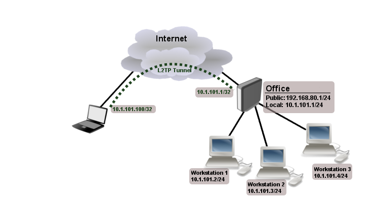
Office router is connected to internet through ether1. Workstations are connected to ether2.
Laptop is connected to the internet and can reach Office router’s public IP (in our example it is 192.168.80.1).
First step is to create a user
[admin@RemoteOffice] /ppp secret> add name=Laptop service=l2tp password=123
local-address=10.1.101.1 remote-address=10.1.101.100
[admin@RemoteOffice] /ppp secret> print detail
Flags: X - disabled
  0   name="Laptop" service=l2tp caller-id="" password="123" profile=default
      local-address=10.1.101.1 remote-address=10.1.101.100

[admin@RemoteOffice] /ppp secret>
Notice that L2TP local address is the same as routers address on local interface and remote address is from the same range as local network (10.1.101.0/24).
Next step is to enable L2TP server and L2TP client on the laptop.
[admin@RemoteOffice] /interface l2tp-server server> set enabled=yes
[admin@RemoteOffice] /interface l2tp-server server> print
            enabled: yes
            max-mtu: 1460
            max-mru: 1460
               mrru: disabled
     authentication: mschap2
    default-profile: default-encryption
[admin@RemoteOffice] /interface l2tp-server server>
L2TP client from the laptop should connect to routers public IP which in our example is 192.168.80.1.
Please, consult the respective manual on how to set up a L2TP client with the software you are using.
Note: By default Windows sets up L2TP with IPsec. To disable IpSec, registry modifications are required. Read more >>
At this point (when L2TP client is successfully connected) if you will try to ping any workstation from the laptop, ping will time out, because Laptop is unable to get ARPs from workstations. Solution is to set up proxy-arp on local interface
[admin@RemoteOffice] interface ethernet> set ether2 arp=proxy-arp
[admin@RemoteOffice] interface ethernet> print
Flags: X - disabled, R - running
  #    NAME                 MTU   MAC-ADDRESS         ARP
  0  R ether1              1500  00:30:4F:0B:7B:C1 enabled
  1  R ether2              1500  00:30:4F:06:62:12 proxy-arp
[admin@RemoteOffice] interface ethernet>
After proxy-arp is enabled client can now successfully reach all workstations in local network behind the router.
Site-to-Site L2TP
The following is an example of connecting two Intranets using a L2TP tunnel over the Internet.
Consider following setup:
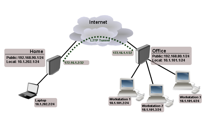
Office and Home routers are connected to internet through ether1, workstations and laptops are connected to ether2.
Both local networks are routed through L2TP client, thus they are not in the same broadcast domain. If both networks should be in the same broadcast domain then you need to use BCP and bridge L2TP tunnel with local interface.
First step is to create a user
[admin@RemoteOffice] /ppp secret> add name=Home service=l2tp password=123
local-address=172.16.1.1 remote-address=172.16.1.2 routes="10.1.202.0/24 172.16.1.2 1"
[admin@RemoteOffice] ppp secret> print detail
Flags: X - disabled
  0   name="Home" service=l2tp caller-id="" password="123" profile=default
      local-address=172.16.1.1 remote-address=172.16.1.2 routes="10.1.202.0/24 172.16.1.2 1"

[admin@RemoteOffice] /ppp secret>
Notice that we set up L2TP to add route whenever client connects. If this option is not set, then you will need static routing configuration on the server to route traffic between sites through L2TP tunnel.
Next step is to enable L2TP server on the office router and configure L2TP client on the Home router.
[admin@RemoteOffice] /interface l2tp-server server> set enabled=yes
[admin@RemoteOffice] /interface l2tp-server server> print
            enabled: yes
            max-mtu: 1460
            max-mru: 1460
               mrru: disabled
     authentication: mschap2
    default-profile: default-encryption
[admin@RemoteOffice] /interface l2tp-server server>
[admin@Home] /interface l2tp-client> add user=Home password=123 connect-to=192.168.80.1 disabled=no
[admin@Home] /interface l2tp-client> print
Flags: X - disabled, R - running
 0 R  name="l2tp-out1" max-mtu=1460 max-mru=1460 mrru=disabled connect-to=192.168.80.1 user="Home"
       password="123" profile=default-encryption add-default-route=no dial-on-demand=no
       allow=pap,chap,mschap1,mschap2
[admin@Home] /interface l2tp-client>
On home router if you wish traffic for the remote office to go over tunnel you will need to add a specific static route as follows:
[admin@Home] /ip route> add dst-address=10.1.101.0/24 gateway=l2tp-out1
After tunnel is established and routes are set, you should be able to ping remote network.
Basic L2TP/IpSec setup
This example demonstrates how to easily setup L2TP/IpSec server on Mikrotik router (with installed 6.16 or newer version) for road warrior connections (works with Windows, Android And iPhones).
First step is to enable L2TP server:
/interface l2tp-server server
set enabled=yes use-ipsec=required ipsec-secret=mySecret default-profile=default
required is set to make sure that only IPSec encapsulated L2TP connections will be accepted.
Now what it does is enables L2TP server and creates dynamic ipsec peer iwth specified secret
[admin@MikroTik] /ip ipsec peer> print
 0  D address=0.0.0.0/0 local-address=0.0.0.0 passive=yes port=500
      auth-method=pre-shared-key secret="123" generate-policy=port-strict
      exchange-mode=main-l2tp send-initial-contact=yes nat-traversal=yes
      hash-algorithm=sha1 enc-algorithm=3des,aes-128,aes-192,aes-256
      dh-group=modp1024 lifetime=1d dpd-interval=2m dpd-maximum-failures=5
Note: Care must be taken if static ipsec peer configuration exists.
Next step is to create VPN pool and add some users.
/ip pool add name=vpn-pool range=192.168.99.2-192.168.99.100

/ppp profile
set default local-address=192.168.99.1 remote-address=vpn-pool

/ppp secret
add name=user1 password=123
add name=user2 password=234
If there are strict firewall policies, do not forget to add rules which accepts l2tp and ipsec.
/ip firewall filter
add chain=input protocol=udp port=1701,500,4500
add chain=input protocol=ipsec-esp
Now router is ready to accept L2TP/IpSec client connections.
L2TP/IpSec with static IPSec server setup
Ipsec/L2TP behind NAT
Consider setup as illustrated below
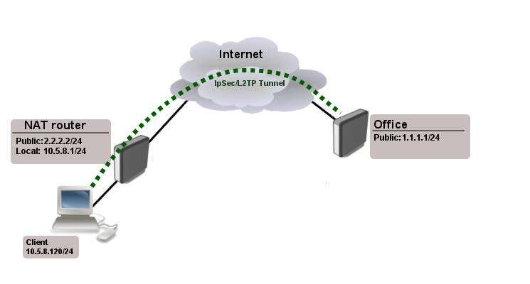
Client needs secure connection to the office with public address 1.1.1.1, but server does not know what will be the source address from which client connects. It is so called road-warrior setup.
Our client will also be located behind the router with enabled NAT.
For the setup RouterOS router will be used as the client device behind NAT (it can be any device: Windows PC, Smartphone, Linux PC, etc.)
IP Connectivity
On the server:
/ip address
add address=1.1.1.1/24 interface=ether1

/ip route
add gateway=1.1.1.2
On the clients router:
/ip address
add address=2.2.2.2/24 interface=ether1
add address=10.5.8.0/24 interface=ether2

/ip route
add gateway=2.2.2.1

/ip firewall nat
add chain=srcnat action=masquerade out-interface=ether1
On the client:
/ip address
add address=10.5.8.120/24 interface=ether1
L2TP Config
On the server:
/interface l2tp-server server
set enabled=yes profil=default

/ip pool
add name=l2tp-pool ranges=192.168.1.2-192.168.1.20

/ppp profile
set default local-address=192.168.1.1 remote-address=l2tp-pool

/ppp secret
add name=l2tp-test password=test123456
On the client:
/interface l2tp-client
add connect-to=1.1.1.1 disabled=no name=l2tp-out1 password=password user=l2tp-test
IpSec Config
On server side:
/ip ipsec proposal
set [ find default=yes ] enc-algorithms=3des,aes-128,aes-192,aes-256
/ip ipsec peer
add generate-policy=yes hash-algorithm=sha1 nat-traversal=yes secret=test123456
RouterOS as client:
/ip ipsec proposal
set [ find default=yes ] enc-algorithms=aes-128
/ip ipsec peer
add address=1.1.1.1/32 hash-algorithm=sha1 nat-traversal=yes secret=test123456

/ip ipsec policy
add dst-address=1.1.1.1/32 protocol=udp sa-dst-address=1.1.1.1 \
      sa-src-address=10.5.8.120 src-address=10.5.8.120/32
Notice that nat-traversal is enabled. This option is required because Ipsec connection will be established through the NAT router otherwise Ipsec will not be able to establish phase2.
Warning: Only one L2TP/IpSec connection can be established through the NAT. Which means that only one client can connect to the sever located behind the same router.
Apple iOS (iPhone/iPad) Client
You must choose L2TP as VPN type in iOS to connect to the IPsec/L2TP server on RouterOS (this includes the default IPsec server created by QuickSet VPN checkbox).
Read More
- BCP (Bridge Control Protocol)
- MikroTik RouterOS and Windows XP IPSec/L2TP
[ Top | Back to Content ]
Configuring a MikroTik L2TP/IPSec VPN Server on MikroTik: A Beginner’s Guide
Introduction
The Layer 2 Tunnelling Protocol (L2TP), combined with Internet Protocol Security (IPSec), provides a secure and efficient VPN solution. This guide will walk you through setting up an MikroTik L2TPVPN server using IPSec on a MikroTik router, ensuring robust security and seamless connectivity.
What is L2TP/IPSec?
L2TP is a VPN protocol used to establish a secure tunnel between two endpoints over the internet. While L2TP itself handles the tunnelling, it does not encrypt the traffic. This is where IPSec comes in—it encrypts the data within the tunnel, ensuring both privacy and security. Together, they form a reliable and widely-supported VPN setup.
Advantages of L2TP/IPSec
- Enhanced Security: Combining L2TP with IPSec ensures strong encryption and authentication, protecting data from interception.
- Cross-Platform Compatibility: Supported by most operating systems, including Windows, macOS, Android, and iOS.
- NAT Traversal: Functions well even in environments using Network Address Translation (NAT), making it versatile for various networks.
- Ease of Configuration: Simple to set up on MikroTik devices using the built-in tools.
Disadvantages of L2TP/IPSec
- Reduced Speeds: The encryption process can lead to slower performance compared to less secure VPN protocols.
- Limited Customisation: Compared to some advanced VPN solutions, L2TP/IPSec offers fewer configuration options.
- Firewall Setup: Requires specific ports to be open (UDP 500, UDP 1701, and UDP 4500), which can be challenging in highly restrictive environments.
Why Use MikroTik for L2TP/IPSec?
MikroTik routers offer a cost-effective and feature-rich platform for setting up VPNs. With their intuitive WinBox interface and extensive documentation, MikroTik devices are an ideal choice for small to medium-sized businesses seeking robust networking solutions.
What You’ll Learn in This Tutorial
- How to enable and configure L2TP on a MikroTik router.
- How to integrate IPSec for secure encryption.
- How to manage user accounts and set up authentication.
- How to test your L2TP/IPSec VPN connection.
By the end of this tutorial, you’ll have a fully operational L2TP/IPSec VPN server ready to provide secure remote access to your network.
Step 1: Configuring the VPN Server
For the server we will be using a MikroTik CHR instnace hosted in AWS, however this can be any Internet-facing MikroTik Router
Click here to see how to provision a MikroTik CHR in AWS using the Free Tier option
Start by navigating to IP > Pool. This step is for creating the IP pool to be given out to the remote clients connecting. For this we give it a name vpn_pool and a range of 10.1.254.10 – 10.1.254.20. This is within the scope of the Bridge we’ve already configured on the CHR (VPN_BRIDGE / 10.1.254.1/24):
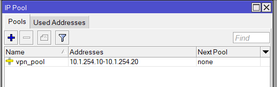
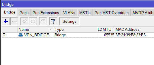
/interface bridge
add name=VPN_BRIDGE protocol-mode=none
/ip pool
add name=vpn_pool ranges=10.1.254.10-10.1.254.20
/ip address
add address=10.1.254.1/24 interface=VPN_BRIDGE network=10.1.254.0Now go to PPP > Profiles and Add a new one and add the following elements:
Name: l2tp-profile
Local Address: 10.1.254.1
Remote Address: vpn_pool
DNS Server: 10.1.254.1 (optional – to use the CHR as the DNS server)
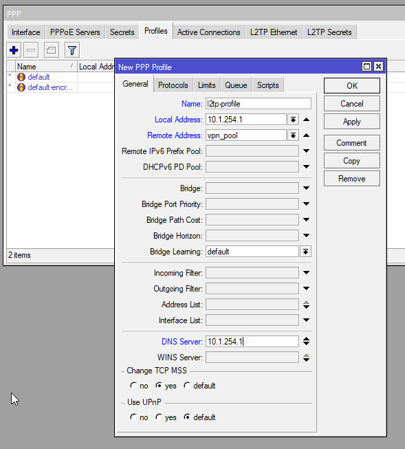
/ppp profile
add dns-server=10.1.254.1 local-address=10.1.254.1 name=l2tp-profile remote-address=vpn_pool
Next is now to enable the L2TP Server:
Enalbed: Yes
Default Profile: l2tp-profile
User IPsec: yes
IPsec Secret: <a strong password>
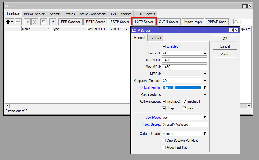
/interface l2tp-server server
set caller-id-type=number default-profile=default enabled=yes use-ipsec=yes  ipsec-secret=Str0ngP@ssWord
Finally configure the client profile:
Name: router-test-01
Password: <password>
Service: l2tp
Profile: l2tp-profile
Local Address: 10.1.254.1
Remote Address: 10.1.254.100 (this could also be the vpn_pool if client IP can be provided dynamically)
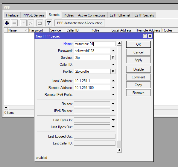
/ppp secret
add local-address=10.1.254.1 name=router-test-01 password=helloworld123 profile=l2tp-profile remote-address=10.1.254.100 service=l2tp
Client Configuration
As we’re doing MikroTik Router to MikroTik Router the client is a MikroTik hAP.
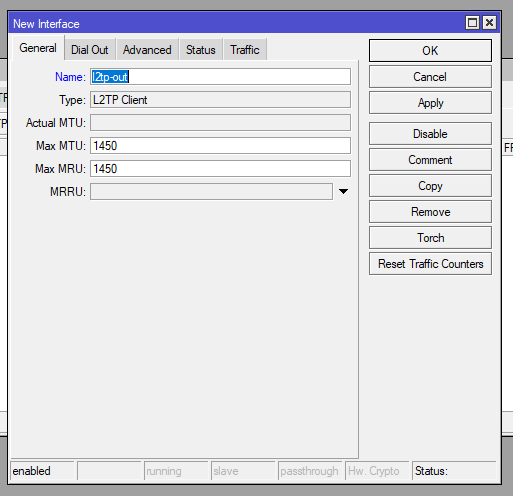
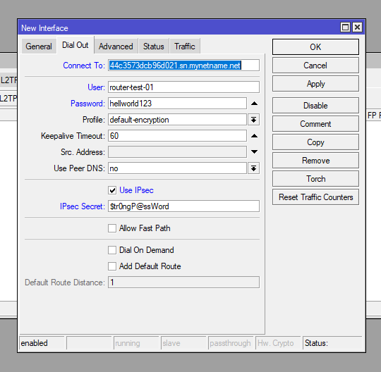
On the client MikroTik go to PPP > Interface and then add a L2TP Client
Add the following on the General and Dial Out tabs:
| General | Dial Out |
| Name: l2tp-out | Connect To: <public IP or DNS name of VPN server> User: router-test-01 Password: <user-password> Use IPsec: Yes IPsec Secret: <L2TP Password> |
/interface l2tp-client
add connect-to=44c3573dcb96d021.sn.mynetname.net disabled=no name=l2tp-out1 use-ipsec=yes user=router-test-01 password=helloworld123 ipsec-secret=Str0ngP@ssWord
Wait a few moments then you’ll see an R appear showing the client is runnig.
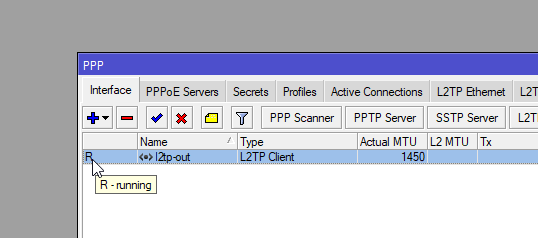
You can then confirm on the server under PPP > Active Connections
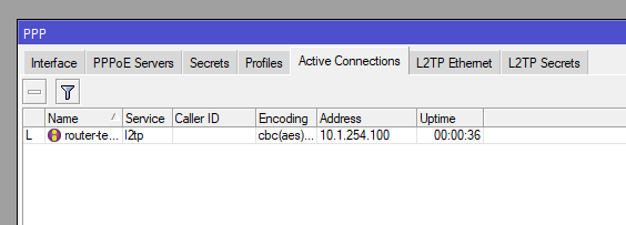
Then you can confirm the Addresses on both VPN server and client
Next Options
Now to confirm routing you can add a static route on each router for the opposite sites LAN address pointing to the L2TP IP address. Watch the YouTube video to see this step.
Продолжая актуальную сегодня тему удаленного доступа, сегодня мы рассмотрим настройку роутеров Mikrotik для использования из в качестве PPTP или L2TP VPN-серверов. С одной стороны тема эта, вроде бы простая, с другой, как обычно, имеет свои особенности, которые следует учитывать еще на стадии выбора решения. Ведь хороший специалист выбирает инструмент под задачу, а не пытается делать наоборот, признавая сильные и слабые стороны каждого решения.
Онлайн-курс по MikroTik
Научиться настраивать MikroTik с нуля или систематизировать уже имеющиеся знания можно на углубленном курсе по администрированию MikroTik. Автор курса, сертифицированный тренер MikroTik Дмитрий Скоромнов, лично проверяет лабораторные работы и контролирует прогресс каждого своего студента. В три раза больше информации, чем в вендорской программе MTCNA, более 20 часов практики и доступ навсегда.
Перед тем, как браться за настройку VPN-сервера на базе Mikrotik мы рекомендуем вам ознакомиться с нашим материалом: Производительность младших моделей Mikrotik hEX и hAP. Экспресс-тестирование. Если коротко: на моделях без аппаратной поддержки AES вы не получите для соединений L2TP/IPsec скоростей более 25-30 МБит/с, на моделях с поддержкой AES скорость упирается в 35-50 МБит/с. В большинстве случаев для сценария удаленного доступа этого достаточно, но все-таки данный момент обязательно следует иметь ввиду, чтобы не получить потом претензию, что Mikrotik работает плохо и этому объективно будет нечего противопоставить.
Что касается PPTP, то здесь все достаточно хорошо, даже недорогие модели роутеров позволяют достигать скоростей около 100 МБит/с, но при этом следует помнить, что PPTP имеет слабое шифрование и не считается безопасным в современных реалиях. Однако он может быть неплохим выбором, если вы хотите завернуть в него изначально защищенные сервисы, например, при помощи SSL.
Предварительная настройка роутера
Прежде чем начинать настройку VPN-сервера нужно определиться со структурой сети и выделить для удаленных клиентов пул адресов. Если брать сценарий удаленного доступа, то здесь есть два основных варианта: Proxy ARP, когда клиенты получают адреса из диапазона локальной сети и имеют доступ к ней без дополнительных настроек и вариант с маршрутизацией, когда клиентам выдаются адреса из диапазона не пересекающегося с локальной сетью, а для доступа в сеть на клиентах добавляются необходимые маршруты. В современных Windows-системах это можно автоматизировать при помощи PowerShell.
После того, как вы определились со структурой сети, следует перейти в IP — Pool и создать новый пул адресов для выдачи удаленным клиентам. Количество адресов в пуле должно соответствовать количеству планируемых VPN-клиентов, либо превышать его.
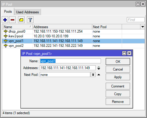
Эти же действия в терминале:
/ip pool
add name=vpn_pool1 ranges=192.168.111.141-192.168.111.149
Затем перейдем в PPP — Profiles и настроим профиль для нашего VPN-сервера, который будет содержать базовые настройки. Если вы настраиваете сразу и PPTP и L2TP-сервера, то можете использовать для них как общий профиль, так и создать отдельные. В случае с общим профилем они будут иметь общий адрес сервера и общий пул адресов. В данном разделе уже существуют два стандартных профиля default и default-encryption, поэтому при желании можете не создавать новые профили, а настроить имеющиеся.
На вкладке General задаем параметры: Local Address — локальный адрес сервера, должен принадлежать к тому же диапазону, что и пул адресов, который вы задали выше, Remote Address — адреса для выдачи удаленным клиентам, указываем в этом поле созданный пул.

Следящая вкладка — Protocols, здесь мы рекомендуем установить параметр Use Encryption в положение required, что будет требовать от клиента обязательного использования шифрования.
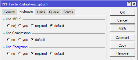
Чтобы добавить новый профиль в терминале выполните (в данном случае мы создаем профиль с именем vpn):
/ppp profile
add change-tcp-mss=yes local-address=192.168.111.140 name=vpn remote-address=vpn_pool1 use-encryption=required
Чтобы изменить существующий default-encryption:
/ppp profile
set *FFFFFFFE local-address=192.168.111.140 remote-address=vpn_pool1 use-encryption=required
Для default вместо set *FFFFFFFE укажите set *0:
/ppp profile
set *0 local-address=192.168.111.140 remote-address=vpn_pool1 use-encryption=required
Остальные параметры оставляем без изменений, для удаленных клиентов они не применяются (в том числе сжатие) и работают только при соединении между устройствами с RouterOS. Отсутствие сжатия также следует учитывать, особенно если ваши клиенты используют медленные каналы подключения, скажем 3G-модемы.
Теперь добавим пользователей, для этого откроем PPP — Secrets и создадим новую учетную запись. Обязательно заполняем поля: Name и Password, а также Profile, где указываем созданный на предыдущем шаге профиль, если профили клиента и сервера не будут совпадать — подключение окажется невозможным. Поле Service позволяет ограничить действие учетных данных только одним сервисом, для этого нужно указать его явно, если же вы хотите использовать одни учетную запись для всех видов подключения — оставьте значение по умолчанию any.
В терминале:
/ppp secret
add name=test1 password=123 profile=default-encryption service=pptp
При создании учетных данных уделите должное внимание политике паролей, особенно для PPTP.
Настройка PPTP-сервера
Настроить PPTP-сервер в RouterOS просто. Откройте PPP — Interface и нажмите кнопку PPTP Server, в открывшемся окне установите флаг Enabled, в поле Default Profile укажите созданный на подготовительном этапе профиль и в разделе Authentication оставьте только mschap2.
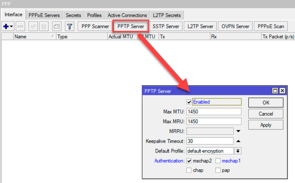
Это же действие в терминале:
/interface pptp-server server
set authentication=mschap2 default-profile=default-encryption enabled=yes
Следующим шагом следует разрешить подключения к нашему VPN-серверу в брандмауэре, для этого следует разрешить входящие подключения для порта 1723 TCP. Открываем IP — Firewall и создаем новое правило: Chain — input, Protocol — tcp, Dst. Port — 1723, в поле In. Interface указываем внешний интерфейс роутера, в нашем случае ether1. Так как действие по умолчанию — accept то просто сохраняем правило.
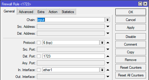
В терминале создать правило можно командой:
add action=accept chain=input dst-port=1723 in-interface=ether1 protocol=tcpНа этом настройку PPTP-сервера можно считать законченной, он готов принимать подключения.
Настройка L2TP/IPsec-сервера
Точно также, как и при настройке PPTP-сервера переходим в PPP — Interface и нажмите кнопку L2TP Server. В открывшемся окне ставим флаг Enabled, в Default Profile указываем созданный ранее профиль, а в Authentication оставляем только mschap2. Затем включаем использование IPsec — Use IPsec — yes и в поле IPsec Secret вводим предварительный ключ соединения:
Для включения сервера с указанными настройками в терминале выполните:
/interface l2tp-server server
set authentication=mschap2 enabled=yes default-profile=default-encryption ipsec-secret=myIPsecPreKey use-ipsec=yes
Обычно на этом инструкции по настройке L2TP-сервера заканчиваются, но если оставить все как есть, то у сервера будут достаточно слабые настройки шифрования, поэтому подтянем их до современного уровня. Для этого нам потребуется изменить параметры IPsec, так как L2TP сервер безальтернативно использует параметры по умолчанию будем менять именно их.
Переходим в IP — IPsec — Proposal и приводим набор настроек default к следующему виду: Auth. Algorithms — sha1, sha256, Encr. Algorithms — aes-128-cbc, aes-192-cbc, aes-256-cbc, PFS Group — ecp384.
Данные настройки в терминале:
/ip ipsec proposal
set [ find default=yes ] auth-algorithms=sha256,sha1 pfs-group=ecp384
Затем откроем IP — IPsec — Profiles и изменим настройки профиля default: Encryption Algorithm — aes256, DH Group — modp2048, ecp256, ecp384.
В терминале:
/ip ipsec profile
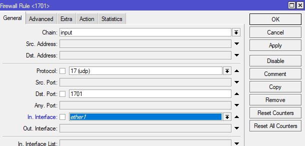
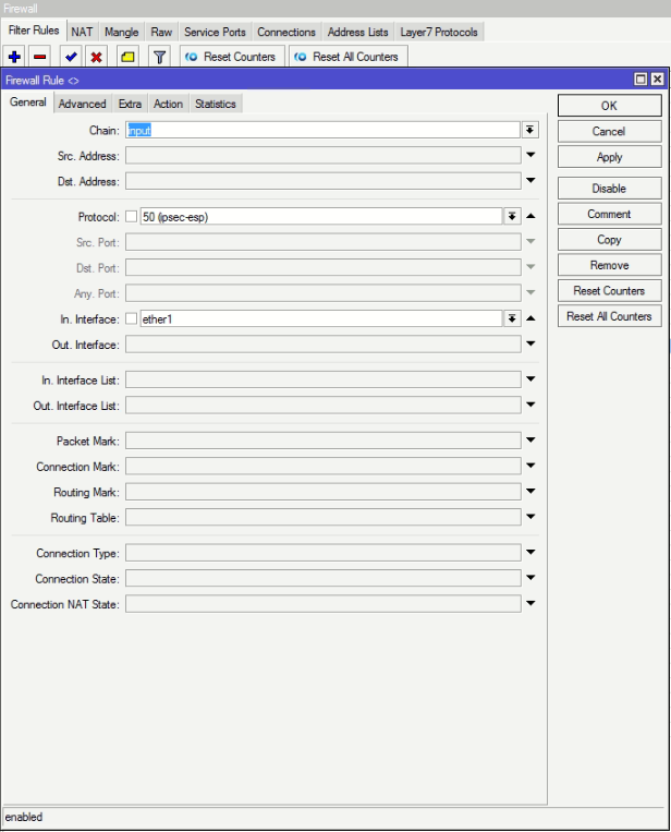
set [ find default=yes ] dh-group=ecp256,ecp384,modp2048 enc-algorithm=aes-256Для окончания настройки разрешим подключения к L2TP-серверу в брандмауэре. Для этого нам понадобится создать два правила, первое должно разрешать подключения для протоколов L2TP (порт 1701 UDP), IKE (порт 500 UDP) и протокола NAT-T (порт 4500 UDP), второе для протокола 50 ESP (Encapsulating Security Payload). Переходим в IP — Firewall и создаем первое правило: Chain — input, Protocol — udp, Dst. Port — 500,1701,4500, в поле In. Interface указываем внешний интерфейс роутера, в нашем случае ether1. Затем второе: Chain — input, Protocol — ipsec-esp, In. Interface -внешний интерфейс (ether1). Так как действие по умолчанию accept достаточно просто сохранить правила.

Для терминала выполните следующие команды:
/ip firewall filter
add action=accept chain=input dst-port=500,1701,4500 in-interface=ether1 protocol=udp
add action=accept chain=input in-interface=ether1 protocol=ipsec-esp
На этом настройка L2TP/IPsec-сервера закончена.
Онлайн-курс по MikroTik
Научиться настраивать MikroTik с нуля или систематизировать уже имеющиеся знания можно на углубленном курсе по администрированию MikroTik. Автор курса, сертифицированный тренер MikroTik Дмитрий Скоромнов, лично проверяет лабораторные работы и контролирует прогресс каждого своего студента. В три раза больше информации, чем в вендорской программе MTCNA, более 20 часов практики и доступ навсегда.
Сегодня расскажу как настроил L2TP на Микротике с авторизацией через Active Directory (AD). Расскажу про 2 схемы реализации доступа к сетям( чуть-чуть про безопасность).
Конечно вы скажите что таких статей куча( пример, пример 2), но я сделал небольшую автоматизацию для пользователей, читайте далее….
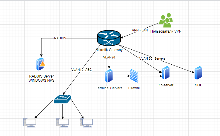
Начнём с описания схемы
Пользователи подключаются к Mikrotik, лучше конечно Mikrotik с аппаратной поддержкой IPsec, это такие модели, как RB730Gr3 или RB4011 или CCR1009, авторизовываясь через AD, для этого нам и потребуется RAIDUS, а далее пользователь должен попадать в сеть для доступа в терминальный сервер( в нашем случаем только в сеть 192.168.10.0/24 vlan 20).
Пользователю запрещено подключаться к нам в сеть и сеть серверов( см. самый последний скриншот).
Начнём создания сети, создаём pool ip которые будем раздавать нашим клиентам
Вот такой диапазон я выбрал, вы же можете взять любой из частных:
Далее создаём PPP профиль IP->PPP->Profiles, DNS я указал -это тоже ip этого микротика, вы можете исходя из этого примера указать 172.16.45.1( это потом нам пригодится), указываем, имя, адрес нашего микротика 172.16.45.1 и выбираем наш только что созданный пул.
Change TCP MSS — yes
Use UPnP можно выбрать no

во вкладке протоколы убираем возможность использования IPv6 (если она у вас есть)
«В PPP Profile оставили Encryption, Compression в default — привет MPPE внутри IPsec», нам этого не надо, поэтому включаем.

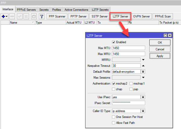
После того как создали профиль возвращаемся в назад и включаем L2TP Server, указываем, всё как на рисунке, только между вторым и третьим шагом нужно выбрать наш только что созданный профиль.
На третьем шаге включаем использование шифрования, что бы наши данные если и смогу перехватить, то не смогли бы расшифровать. на четвёртом шаге указываем наш ключ IPsec (чем длиннее, тем лучше)
«Pre Shared Key для IKE AUTH должен быть не менее 32 символов и создан с энтропией не менее 256 бит.
IKE Aggressive exchange необходимо запретить для избегания Offline Dictionary Attack на ваш PSK.»
Called ID Type у меня указано ip address, а так же я чуть позже поставил галочку одна сессия на хост (но если работает из под NAT, то больше чем 1 клиент всё равно не подключится)
в Default-Profile указываем наш профиль см. рисунок

«Если вы не уменьшите MTU до fail-safe 1400, то будет выполняться fragmentation after encapsulation, а это приводит к низкой производительности IPsec туннеля.
То есть мы инкапсулируем IP пакет в PPP кадр, далее в L2TP пакет, далее в UDP, потом в ESP, потом если повезёт сразу в IP, если нет снова в UDP и потом в IP, последний этап потребует выполнить фрагментацию поскольку итоговый размер UDP/ESP будет превышать MTU.»
Очевидно, что причина этого — сложный путь обработки трафика, который полностью ложится на плечи CPU. Можно ли этого как-либо избежать? Можно, в RouterOS v6 для этого появилась новая технология — Fast Path (быстрый путь), которая позволяет направить трафик по быстрому пути, без обработки ядром ОС, что позволяет существенно снизить нагрузку на систему.
Основная мысль, положенная в основу этой технологии такова, что пакеты уже установленных соединений, а также тех участков передачи трафика, где не требуется фильтрация и контроль, можно отправить по быстрому пути, тем самым разгружая процессор и ускоряя передачу данных. Fast Path — это расширение драйвера интерфейса, которое позволяет ему напрямую взаимодействовать с некоторыми подсистемами RouterOS и пропускать остальные.
Авторизовывать пользователей мы будем через Windows Active Directory, для этого нам потребуется Radius, переходим
IP->PPP->Secrets и как указано на рисунке включаем Radius аутентификацию

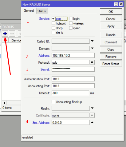
Далее нам потребуется настроить работу Radius, начнём со стороны Микротик, как показано на рисунке ниже, радиус будет использоваться только для PPP соединений,
-
указываем ip нашего сервера с развёрнутой службой NPS на Windows Server, в нашем случае это 192.168.10.2
-
Придумываем ключ для работы Radius ( взаимодействия Mikrotik и NPS) это не тот ключ, что мы придумывали IPsec
-
Source IP address of the packets sent to RADIUS server оставляем 0.0.0.0/0
2. Настройка Windows Server
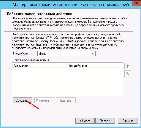
Для начала добавим новую роль, это «Сервер политики сети» (NPS), требуется для разворачивания Radius сервера, пошаговая инструкция ниже.

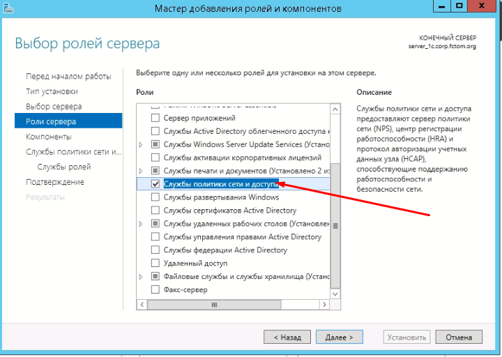

А так же нам потребуется пакет администрирования CMAK

Запускаем NPS,

Регистрируем сервер а Active Directory

Если работаем с Mikrotik, то достаточно оставить только порты 1812 и 1813

Создаём RADIUS клиента

В нашем случае, это будет Mikrotik, указываем его ip адрес, у нас это шлюз, в пунктах 3,4 (см. рисунок) указываем секретную фразу которую будем использовать для подключения клиента

Идём на контроллер AD, создаём группу доступа к VPN, добавляем в неё пользователей, кто будет иметь доступ к подключению.

Вернёмся в NPS.
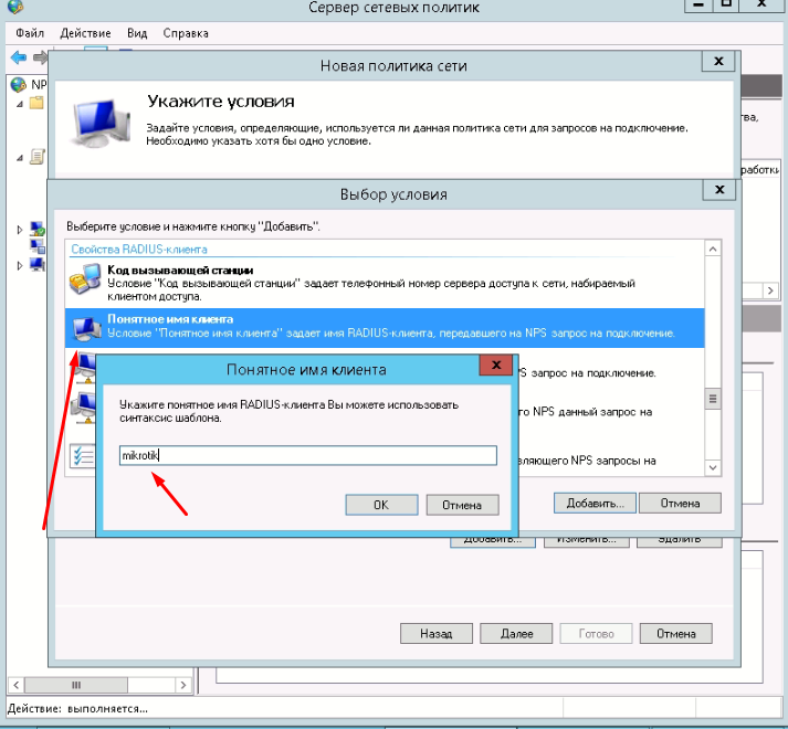
Идём в «Политики->Сетевые политики», создаём новую


Указываем в политиках, что пускать будем конкретную группу.


Указываем нормальное имя клиента, что бы боты не подключались

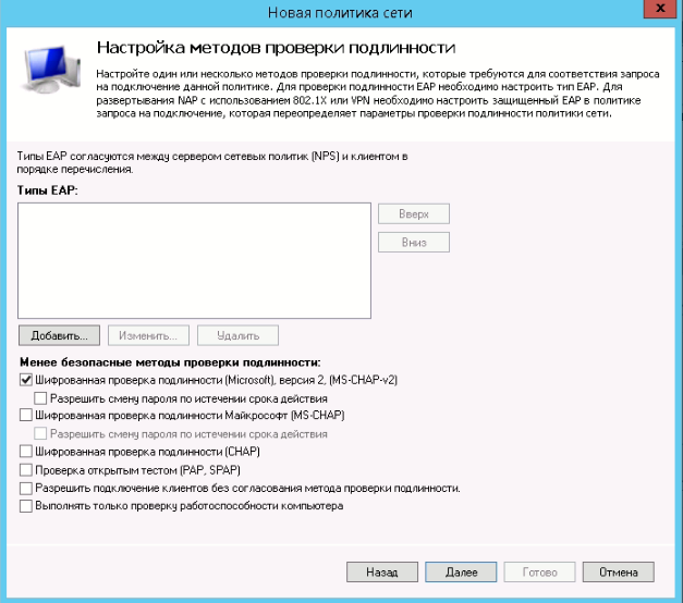
Проверка подлинности будет MS-CHAP-v2, EAP- сертификаты не используем, кто хочет может развернуть центр сертификации и выдавать сертификаты, но это совсем другая история…


Создаём политику запросов

Ограничим работу VPN по дням недели и времени суток( нечего нас ломать пока мы спим)

я запретил работу с 1 ночи до 5 утра и в воскресенье


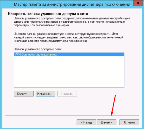
3. Настройка клиентского пакета через CMAK
учтите если требуется создание пакета для 32-bit систем, то потребуется установить CMAK на машинке 32bit и на ней проделать те же самые манипуляции
Далее пошаговые скриншоты по созданию пакета


заходим в настройки
Указываем IPsec ключ в раздел и «общий ключ» тот что из раздела настройки Mikrotik (см.выше)
Придумываем ПИН-код для запуска данного приложения, этот пин мы будем сообщать пользователю вместо длинного пароля IPsec. У меня пин это что-то не сложное например:
#You2021Company!, где YouCompany название вашей компании.


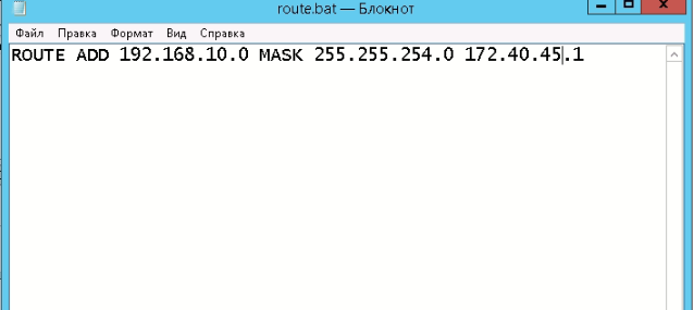
И вот тут как раз та заковырочка, здесь мы указываем «батничек» с маршрутом, что бы пользователь прозрачно попадал и работал с той сетью, которую мы хотим ему предоставить.
Вот что указано в нашем route.bat
Если хотите, то можно забрендировать, под стиль компании, указать логитип

Указываем файл-соглашение для пользователя (что-то пугающее, что бы свои пароли никому не разглашали!)

По данному пути у нас создаётся рабочий пакет, запаковываем его в zip и закидываем к себе на сайт, и всех пользователей направляем туда, а так же на сайте можно сделать инструкцию, что бы пользователь мог определить нужен ему 32 или 64битный пакет.

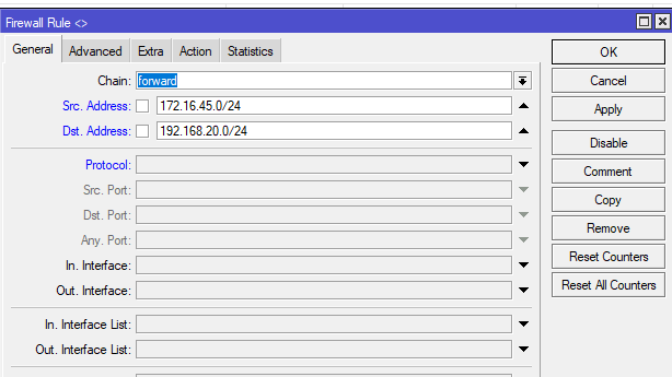
Настройка Firewall
Создаём правило в Микротике

Исключение из NAT L2TP клиентов через ipsec:out не требуется, это актуально только для транзитного трафика и чистого IPsec. Поскольку XFRM lookup выполняется после SNAT, для L2TP клиентов RD выполняется раньше чем SNAT, а после инкапсуляции L2TP в ESP, трафик порождается локально и в SNAT не попадает.»
 указываем что мы \"НЕ НАТИМ\"!")
Запрещаем взаимодействие сете между собой ip->firewall->вкладка rules, ставим значение действий «drop».

Вот и всё, теперь можно проверять, закидываем пользователя в доменную группу, скачиваем zip пакет, устанавливаем и пробуем авторизоваться.
Использовал следующие публикации:
-
https://xn—-7sba7aachdbqfnhtigrl.xn--j1amh/nastrojka-mikrotik-ipsec-vpn-tunnel-mezhdu-ofisami/
-
спасибо@zanswer за продуктивную критику, всё что рекомендовали-исправил
Материал из MikroTik Wiki
В статье разбирается настройка L2TP- и L2TP/IPSec-туннеля на оборудовании MikroTik с целью подключения рабочего места сотрудника (client-to-site VPN). После создания VPN-канала между сетями будет работать маршрутизация и будет выполнена проверка работоспособности. Также будут разобраны типичные проблемы, которые могут возникнуть в процессе настройки и проверки.
Схема сети

В головном офисе установлен маршрутизатор GW1. Он же будет настроен в качестве VPN-сервера. В этом же офисе работает сервер DC1, который является контроллером домена и параллельно выполняет функции DNS и WINS-сервера. К головному офису будет подключаться компьютер, который будет настроен как VPN-клиент.
Головной офис
IP-адрес внешней сети головного офиса: 10.1.100.0/24
IP-адрес внешнего интерфейса маршрутизатора GW1: 10.1.100.1/24
IP-адрес внутренней сети головного офиса: 192.168.15.0/24
IP-адрес внутреннего интерфейса маршрутизатора GW2: 192.168.15.1/24
IP-адрес сервера DC1: 192.168.15.10/24
Удаленный компьютер
IP-адрес удаленного компьютера: 10.1.200.1/24
VPN-канал
IP-адрес VPN-интерфейса маршрутизатора GW1: 172.16.30.101/32
Пулл адресов VPN-канала: 172.16.30.102 — 172.16.30.253
Полезные материалы по MikroTik
На Telegram-канале Mikrotik-сэнсей можно получить доступ к закрытой информации от официального тренера MikroTik. Подписывайтесь

ИП Скоромнов Дмитрий Анатольевич, ИНН 331403723315
Настройка
Настройка маршрутизатора
Через графический интерфейс
Включить L2TP-сервер. Не смотря на то, что L2TP не несет в себе нормального шифрования, лучше оставить только аутентификацию «mschap2» как наиболее надежную.

Создать пул адресов для VPN-подключений:

Создать профиль для VPN подключений. Указать адрес сервера DC1, который является DNS и WINS сервером. Без указания DNS и WINS VPN-подключение произойдет, но не будет возможности обращаться к узлам по именам.

Добавить аккаунт пользователя:

На интерфейсе маршрутизатора, который смотрит в локальную сеть включить arp-proxy. Это нужно для того, чтобы удаленный клиент мог связываться с локальными хостами:

Создать профиль IPSec для подключения клиента (адрес 0.0.0.0/0 т.к. удаленный адрес клиента неизвестен):

Через консоль
/interface l2tp-server server
set authentication=mschap2 enabled=yes
/ip pool
add name=vpn-pool ranges=172.16.30.102-172.16.30.253
/ppp profile
add name="L2TP client-to-site" change-tcp-mss=yes local-address=172.16.30.101 remote-address=vpn-pool dns-server=192.168.15.10 wins-server=192.168.15.10
/ppp secret
add name=user-laptop password=user-laptop-password profile="L2TP client-to-site" service=l2tp
/interface ethernet
set ether1-LAN1 arp=proxy-arp
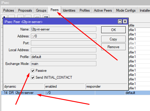
/ip ipsec peer
add address=0.0.0.0/0 comment=client-to-site enc-algorithm=3des,aes-128,aes-256 exchange-mode=main-l2tp generate-policy=port-strict nat-traversal=yes secret=ipsec-password send-initial-contact=no auth-method=pre-shared-key
Настройка маршрутизации
Не требуется.
Следует учесть
- AES является единственным алгоритмом, который поддерживается модулем аппаратного шифрования, если такой установлен на маршрутизатор.
- Если требуется подключение только по L2TP без IPsec, то достаточно пропустить последний пункт по настройке IPsec. При этом надо учесть, что встроенный VPN-клиент Windows не поддерживает подключение по L2TP без IPSec. Для того, чтобы такое подключение заработало необходимо править реестр операционной системы.
Проверка
Для того, что бы проверить VPN-соединение достаточно запустить ping с компьютера VPN-клиента на любой компьютер в сети за маршрутизатором GW1.
Типичные проблемы
- Если VPN-соединение не устанавливается, то надо проверить:
- Не мешает ли файервол. Для уверенности лучше временно отключить все правила файервола на маршрутизаторе.
- Совпадают ли имя пользователя, пароль и ключ IPsec.
- На VPN-клиенте указан правильный адрес VPN-сервера к которому должно происходить подключение.
Полезные материалы по MikroTik
На Telegram-канале Mikrotik-сэнсей можно получить доступ к закрытой информации от официального тренера MikroTik. Подписывайтесь

ИП Скоромнов Дмитрий Анатольевич, ИНН 331403723315