
В этом документе рассказывается, как создать VPN типа Host-to-LAN от встроенного VPN-клиента Windows 7 до маршрутизатора Vigor. В этом примере мы используем L2TP через IPsec VPN. Содержимое будет состоять из двух частей: настроить Vigor Router в качестве VPN-сервера и подключить VPN из Windows 7.
Конфигурация маршрутизатора Vigor
1. Создайте профиль пользователя удаленного подключения в VPN and Remote Access >> Remote Dial-In User
- Установите флажок Enable this account.
- Введите имя Username и Password.
- Выберите политику L2TP и IPsec как Must.

2. Введите общий ключ в разделе VPN and Remote Access >> IPsec General Setup .
Настройка VPN в Windows 7
1. Установите новое подключение или сеть в Панель управления >> Центр управления сетями и общим доступом .
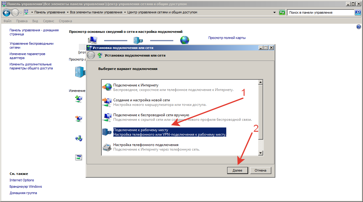
2. Выберите Подключиться к рабочему месту и нажмите Далее .
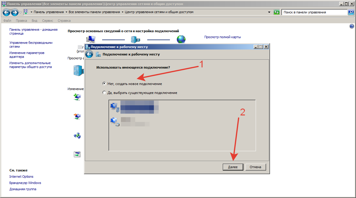
3. Выберите «Создать новое подключение » и нажмите « Далее » .
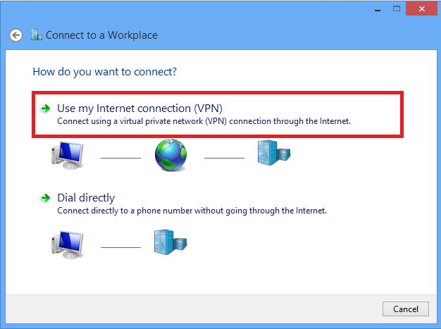
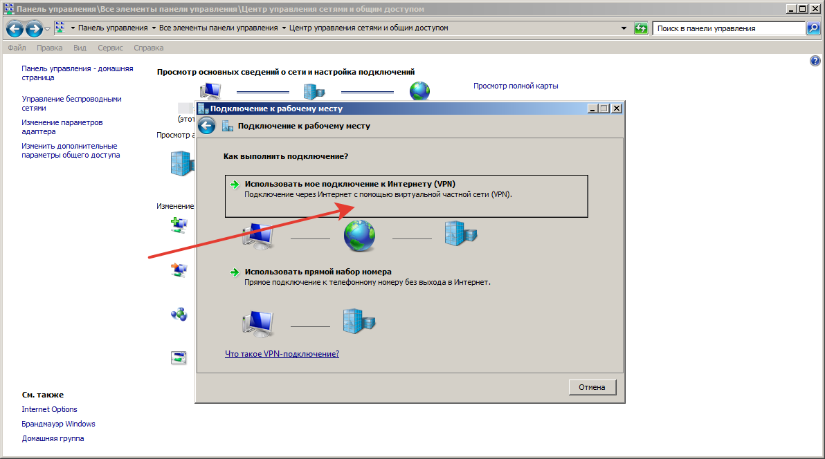
4. Выберите Использовать мое подключение к Интернету .
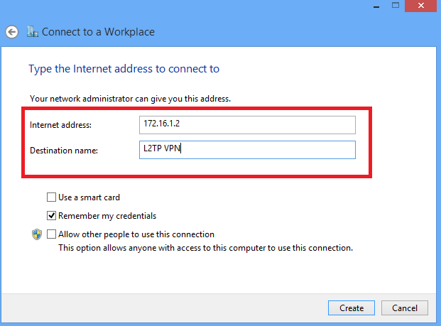
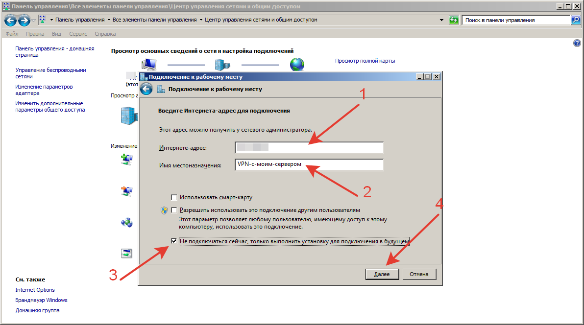
5. Введите IP-адрес WAN маршрутизатора Vigor в адрес Интернет , установите флажок « Не подключаться сейчас » и нажмите « Далее » .
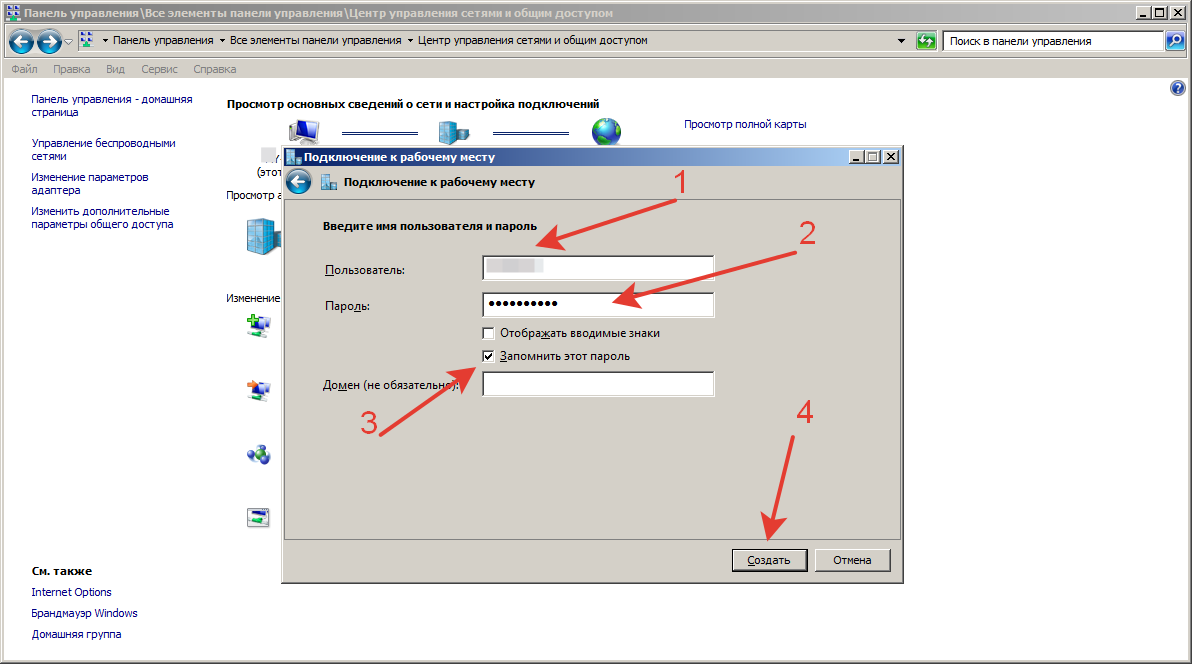
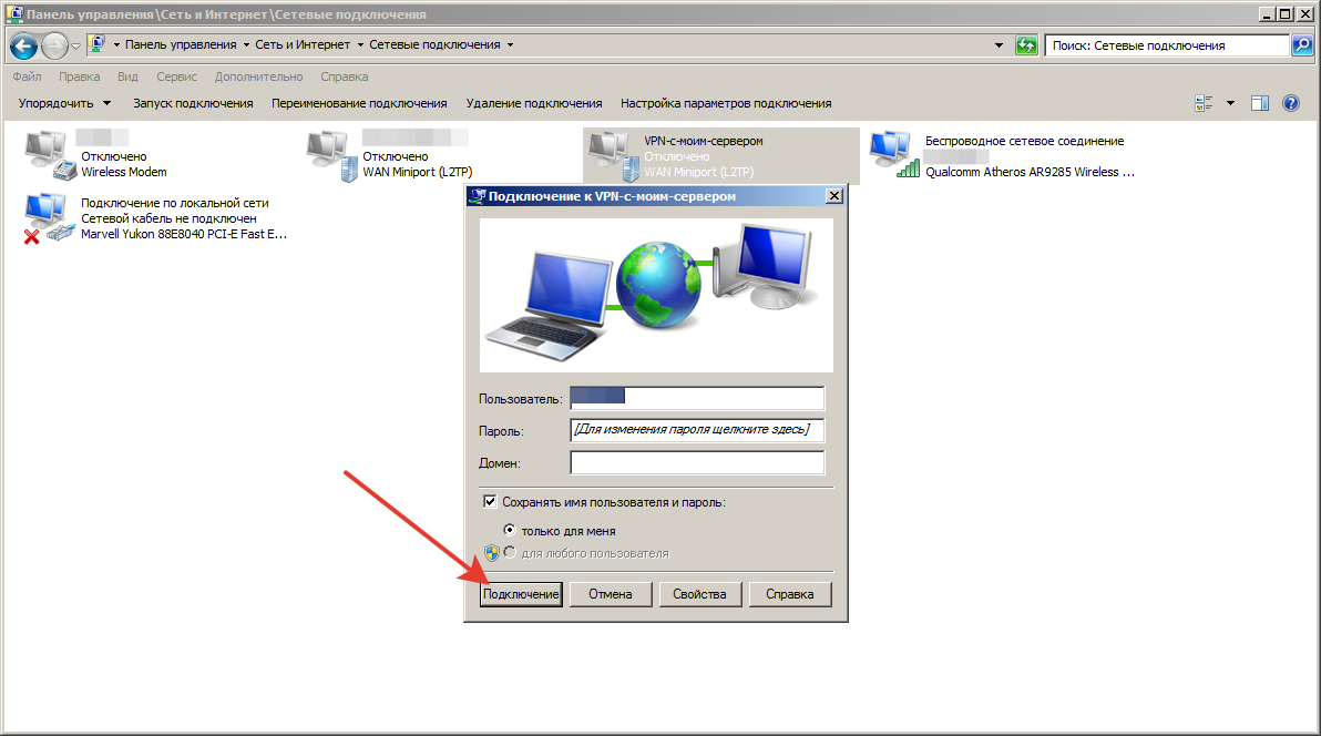
6. Введите имя пользователя и пароль для подключения L2TP VPN и нажмите « Создать » .
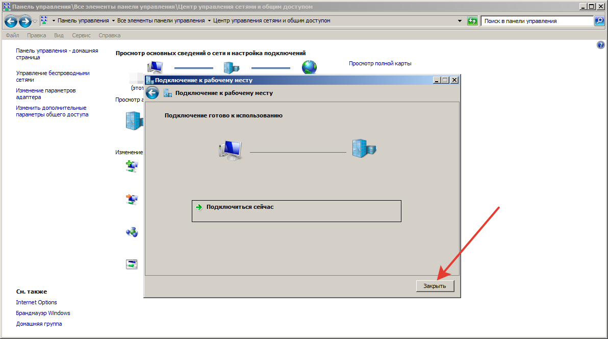
7. Не нажимайте Подключить сейчас, а вместо этого щелкните Закрыть .

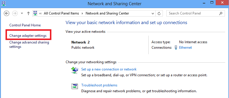
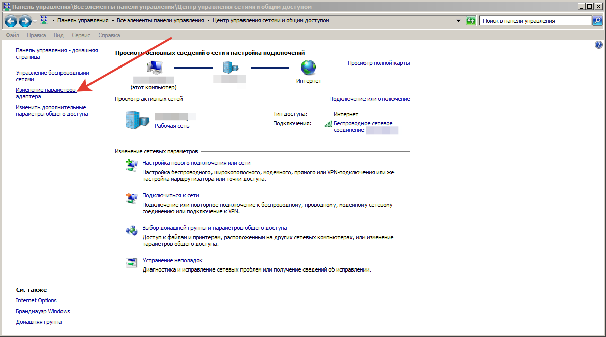
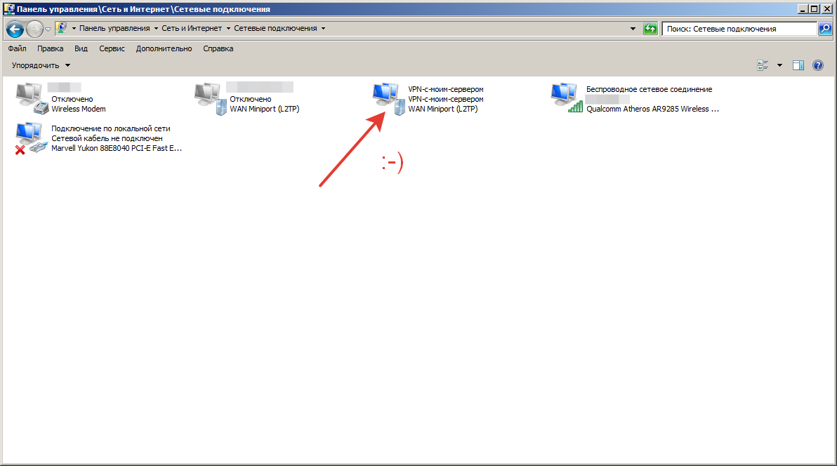
8. Щелкните Изменить параметры адаптера в Панели управления >> Центр общего доступа к сети .
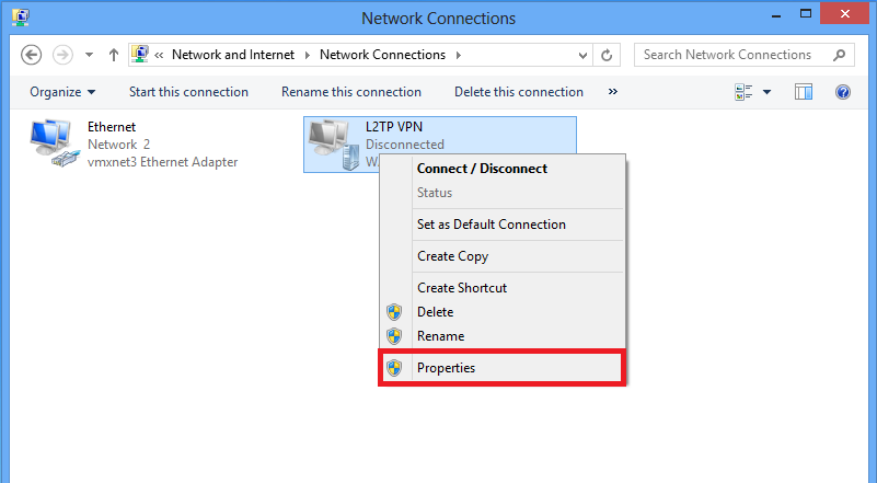
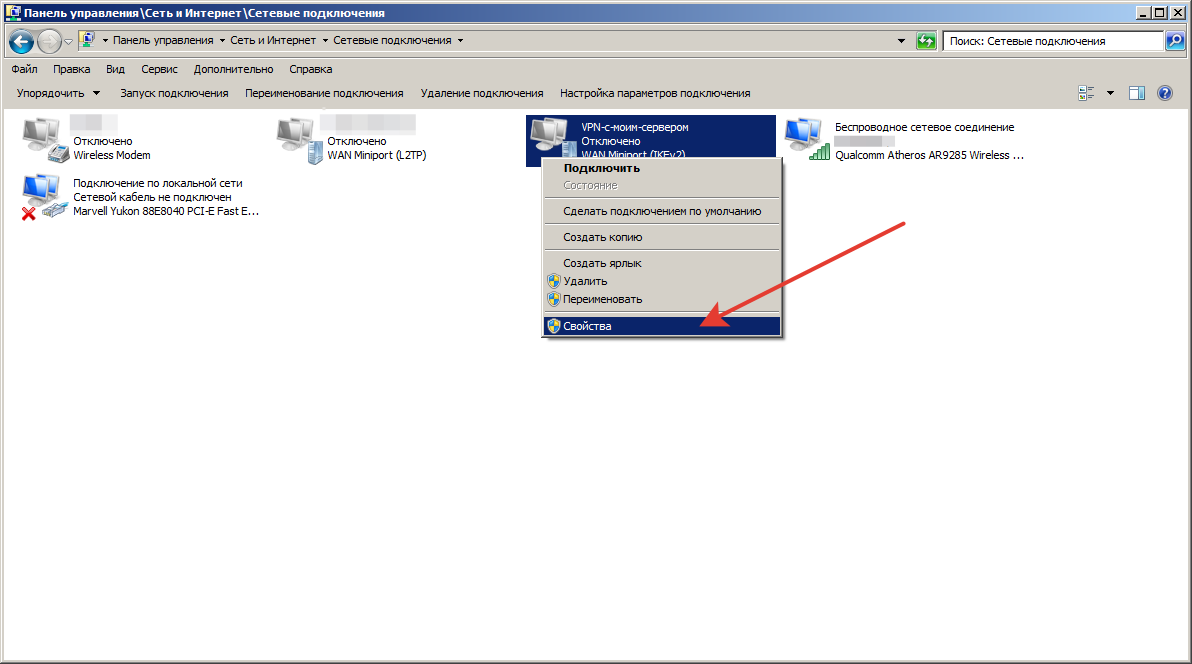
9. Щелкните правой кнопкой мыши L2TP через соединение IPSec, которое мы создали, и выберите Свойства .

10. Выберите тип VPN как L2TP/IPSec на вкладке «Безопасность», а затем нажмите « Дополнительные параметры » .
11. Выберите « Использовать общий ключ для аутентификации », введите ключ и нажмите « ОК». Ключ должен совпадать с настройкой Pre-Shared Key на Vigor Router.
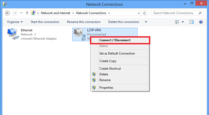
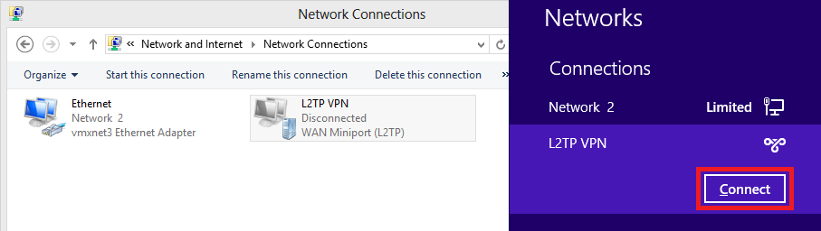
12. Щелкните правой кнопкой мыши L2TP через соединение IPSec и выберите Подключиться.

13. Введите имя пользователя и пароль и нажмите « Подключиться » . Имя пользователя и пароль должны быть такими же, как в профиле пользователя VPN Remote Dial-In на маршрутизаторе.
14. Теперь установлено соединение L2TP через IPSec.
Исправление проблем:
Если туннель L2TP через IPSec от Windows 7 до маршрутизатора Vigor не может быть успешно установлен, проверьте приведенные ниже настройки.
- Перейдите в Панель управления >> Администрирование >> Службы и убедитесь, что служба агента политики IPSec запущена.
- Перейдите в Панель управления l>> Администрирование >> Службы , убедитесь, что модули ключей IKE и AuthIP IPSec запущены.
- Откройте Regedit и проверьте, равно ли значение ProhibitIpSec 0 в реестре Windows >> HEKY_LOCAL_MACHINE >> SYSTEM >> CurrentControlSet >> services >> RasMan >> Parameters >> ProhibitIpSec. Если это не так, измените значение на 0 и перезапустите Windows 7, чтобы повторить попытку.
07.11.2019
Инструкция: Настройка L2TP/IPSec подключения в ОС Windows
Для клиентов ИТ аутсорсинга мы составляем инструкции по самостоятельной настройке оборудования, данные рекомендации позволяют пользователям произвести настройку в удобное время, например, настроить удаленное подключение домашнего компьютера к рабочей сети.
Вводные данные
Для настройки L2TP/IPSEC VPN-подключения Вам потребуются следующие данные:
- IP-адрес, либо доменное имя VPN-сервер
- Логин VPN-пользователя
- Пароль VPN-пользователя
- Общий ключ шифрования
Эти данные Вы можете получить у контактного лица в Вашей компании.
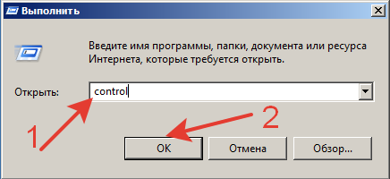
В зависимости от версии ОС Windows, установленной на Вашем ПК, внешний вид меню настройки VPN-подключения будет различаться. Для того, чтобы определить версию Windows, находясь на рабочем столе системы, одновременно зажмите комбинацию клавиш Win (клавиша с изображением логотипа Windows) + R. В появившемся окне «Выполнить», введите команду «winver» (без кавычек):

Откроется окно «Windows: сведения», в котором будет указана версия Вашей операционной системы:

После того, как Вы выяснили версию Вашей ОС, перейдите к соответствующему ей разделу инструкции.
Настройка VPN-подключения в Windows 10
Нажмите правой кнопкой мыши на кнопке меню «Пуск» и выберите из контекстного меня пункт «Параметры»:
В окне «Параметры» выберите раздел «Сеть и Интернет», затем выберите из списка пункт «VPN» и нажмите кнопку «Добавить VPN-подключение»


В окне настроек VPN-подключения, укажите следующие значения:
- Поставщик услуг VPN – Windows (встроенные)
- Имя подключения – любое понятное Вам название данной VPN-сети (на технические свойства настраиваемой сети никак не влияет)
- Адрес или имя сервера – IP-адрес, либо доменное имя VPN-сервера
- Тип VPN – L2TP/IPsec с предварительным ключом
- Общий ключ – Общий ключ шифрования
- Тип данных для входа – Имя пользователя и пароль
- Имя пользователя – Логин VPN-пользователя
- Пароль – Пароль VPN-пользователя
После ввода данных нажмите кнопку «Сохранить»:

Чтобы подключиться к добавленной сети, в правом нижнем углу экрана (рядом с часами и значком или ), кликните по нему левой кнопкой мыши, выберите из списка VPN-сеть и нажмите кнопку «Подключить» (отключение производится тем же способом):
Об успешном подключении говорит надпись «Подключено», под названием VPN-подключения:
Прим.: опционально для настройки может быть указано, что необходимо отключить «Шлюз в удалённой сети». Для выполнения этой настройки перейдите к соответствующему разделу данной инструкции
Настройка VPN-подключения в Windows 8.1 / Windows 7
Находясь на рабочем столе системы, одновременно зажмите комбинацию клавиш Win (клавиша с изображением логотипа Windows) + R. В появившемся окне «Выполнить», введите команду «control» (без кавычек):

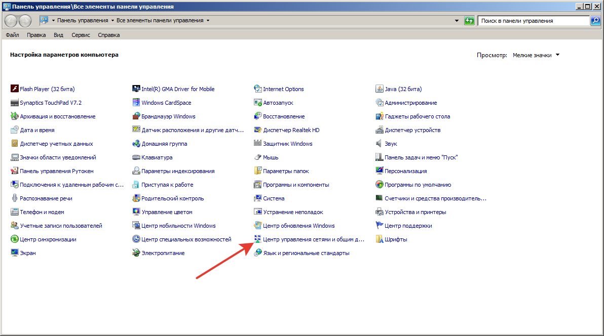
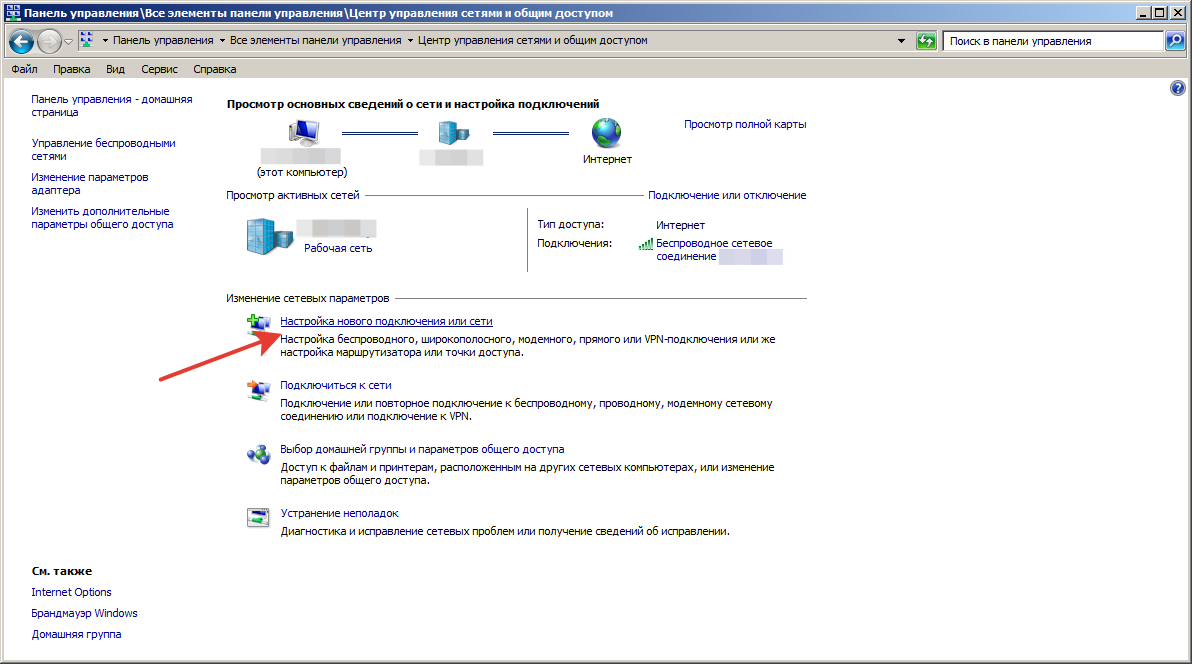
Откройте мастер создания нового подключения («Сеть и Интернет –> Центр управления сетями и общим доступом –> Центр управления сетями и общим доступом –> Создание и настройка нового подключения или сети»):


Следуйте указаниям мастера, как указано на изображениях ниже:


В окне настроек VPN-подключения, укажите следующие значения:
- Адрес в Интернете – IP-адрес, либо доменное имя VPN-сервер
- Имя объекта назначения – любое понятное Вам название данной VPN-сети (на технические свойства настраиваемой сети никак не влияет)
- Нажмите кнопку «Создать»


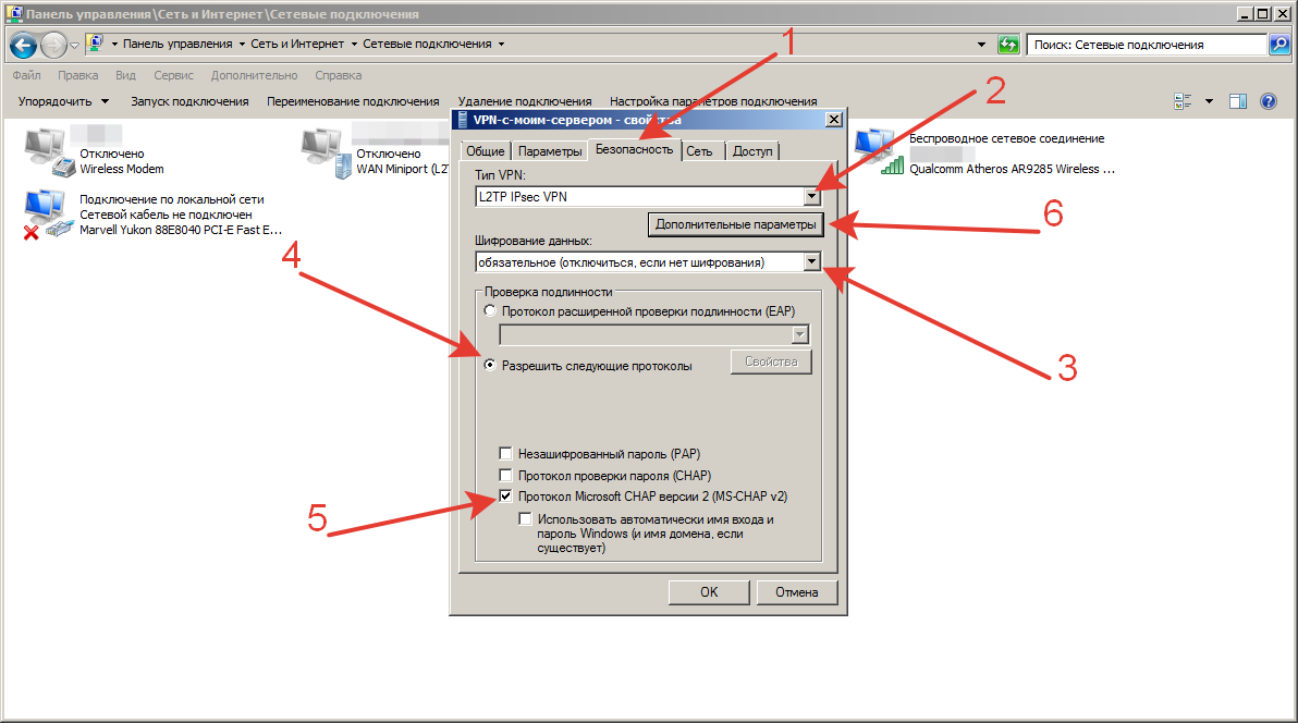
В окне свойств подключения, перейдите на вкладку «Безопасность» и нажмите кнопку «Дополнительные параметры»:

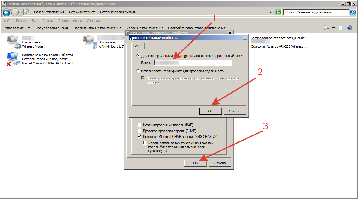
В окне дополнительных свойств, отметьте пункт «Для проверки подлинности использовать общий ключ» и в поле «Ключ» введите общий ключ шифрования, нажмите кнопку «Ок»:

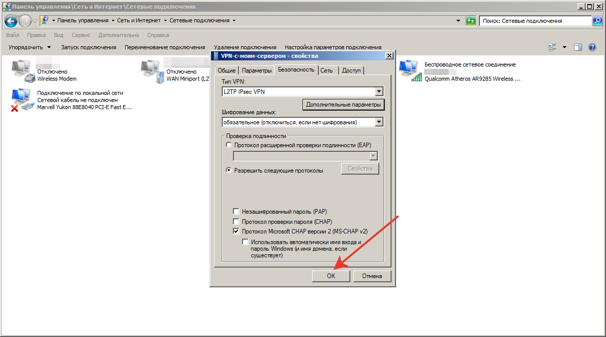
В основном окне свойств подключения, настройте следующие параметры:
- Тип VPN – Протокол L2TP с IPsec (L2TP/IPsec)
- Шифрование данных – обязательное (отключиться, если нет шифрования)
- Разрешить следующие протоколы – Протоколы Microsoft CHAP версии 2 (MS-CHAP v2)

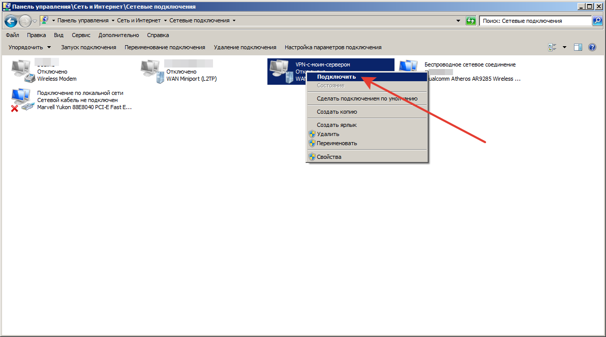
Чтобы подключиться к добавленной сети, в правом нижнем углу экрана (рядом с часами и значком раскладки клавиатуры), найдите значок с изображением сетевого подключения ( или ), кликните по нему левой кнопкой мыши, выберите из списка VPN-сеть и нажмите кнопку «Подключить» (отключение производится тем же способом):
Рисунок 1. Вид окна подключения в Windows 8.1
Рисунок 2. Вид окна подключения в Windows 7
Об успешном подключении говорит надпись «Подключено», под названием VPN-подключения:
Для отключения от VPN нажмите кнопку «Отключить»:
Прим.: опционально для настройки может быть указано, что необходимо отключить «Шлюз в удалённой сети». Для выполнения этой настройки перейдите к соответствующему разделу данной инструкции.
Как отключить шлюз в удаленной сети
Находясь на рабочем столе системы, одновременно зажмите комбинацию клавиш Win (клавиша с изображением логотипа Windows) + R. В появившемся окне «Выполнить», введите команду «control» (без кавычек):
В открывшемся окне «Все элементы панели управления» последовательно перейдите в разделы «Центр управления сетями и общим доступом» -> «Изменения параметров адаптера», кликните правой кнопкой мыши по ярлыку Вашего VPN-подключения и из контекстного меню выберите пункт «Свойства»:

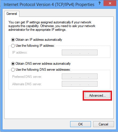
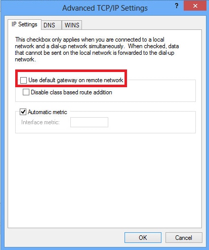
В окне свойств VPN-подключения перейдите на вкладку «Сеть», выделите мышью компонент «IP версии 4 (TCP/IPv4)», нажмите кнопку «Свойства», в следующем окне нажмите кнопку «Дополнительно», в открывшемся окне «Дополнительные параметры TCP/IP» снимите галочку с пункта «Использовать основной шлюз в удалённо сети» и нажимайте кнопку «Ок» во всех открытых на предыдущих шагах окнах.

Introduction
This document describes how to configure Layer 2 Tunneling Protocol (L2TP) over IPsec using pre-shared key between Cisco Adaptive Security Appliance (ASA) and Windows 8 native client.
L2TP over Internet Protocol security (IPsec) provides the capability to deploy and administer an L2TP Virtual Private Network (VPN) solution alongside the IPsec VPN and firewall services in a single platform.
Prerequisites
Requirements
Cisco recommends that you have knowledge of these topics:
- IP connectivity from the client machine to the ASA. To test connectivity, try to ping the IP address of the ASA from client endpoint and vice versa
- Ensure that UDP port 500 and 4500 and Encapsulating Security Payload (ESP) protocol is not blocked anywhere along the path of the connection
Restrictions
- L2TP over IPsec supports only IKEv1. IKEv2 is not supported.
- L2TP with IPsec on the ASA allows the LNS to interoperate with native VPN clients integrated in such operating systems as Windows, MAC OS X, Android, and Cisco IOS. Only L2TP with IPsec is supported, native L2TP itself is not supported on ASA.
- The minimum IPsec security association lifetime supported by the Windows client is 300 seconds. If the lifetime on the ASA is set to less than 300 seconds, the Windows client ignores it and replaces it with a 300 second lifetime.
- The ASA only supports the Point-to-Point Protocol (PPP) authentications Password Authentication Protocol (PAP) and Microsoft Challenge-Handshake Authentication Protocol (CHAP), Versions 1 and 2, on the local database. Extensible Authentication Protocol (EAP) and CHAP are performed by proxy authentication servers. Therefore, if a remote user belongs to a tunnel group configured with the authentication eap-proxy or authentication chap commands, and the ASA is configured to use the local database, that user cannot connect.
Supported PPP Authentication Types
L2TP over IPsec connections on the ASA support only the PPP authentication types shown in Table
|
AAA Server Support and PPP Authentication Types |
|
|
AAA Server Type |
Supported PPP Authentication Types |
|
LOCAL |
PAP, MSCHAPv1, MSCHAPv2 |
|
RADIUS |
PAP, CHAP, MSCHAPv1, MSCHAPv2, EAP-Proxy |
|
TACACS+ |
PAP, CHAP, MSCHAPv1 |
|
LDAP |
PAP |
|
NT |
PAP |
|
Kerberos |
PAP |
|
SDI |
SDI |
|
PPP Authentication Type Characteristics |
||
|
Keyword |
Authentication Type |
Characteristics |
|
chap |
CHAP |
In response to the server challenge, the client returns the encrypted [challenge plus password] with a clear text username. This protocol is more secure than the PAP, but it does not encrypt data. |
|
eap-proxy |
EAP |
Enables EAP which permits the security appliance to proxy the PPP authentication process to an external RADIUS authentication server. |
|
ms-chap-v1 ms-chap-v2 |
Microsoft CHAP, Version 1 Microsoft CHAP, Version, 2 |
Similar to CHAP but more secure in that the server stores and compares only encrypted passwords rather than clear text passwords as in CHAP. This protocol also generates a key for data encryption by MPPE. |
|
pap |
PAP |
Passes clear text username and password during authentication and is not secure. |
Components Used
The information in this document is based on these software and hardware versions:
- Cisco 5515 Series ASA that runs the software version 9.4(1)
- L2TP/IPSec client (Windows


The information in this document was created from the devices in a specific lab environment. All of the devices used in this document started with a cleared (default) configuration. If your network is live, ensure that you understand the potential impact of any command.
Related Products
This configuration can also be used with Cisco ASA 5500 series Security Appliance 8.3(1) or later.
Conventions
Refer to Cisco Technical Tips Conventions for more information on document conventions
Background Information
Layer 2 Tunneling Protocol (L2TP) is a VPN tunneling protocol that allows remote clients to use the public IP network to securely communicate with private corporate network servers. L2TP uses PPP over UDP (port 1701) to tunnel the data.
L2TP protocol is based on the client/server model. The function is divided between the L2TP Network Server (LNS), and the L2TP Access Concentrator (LAC). The LNS typically runs on a network gateway such as the ASA in this case, while the LAC can be a dial-up Network Access Server (NAS) or an endpoint device with a bundled L2TP client such as Microsoft Windows, Apple iPhone, or Android.
Configure
This section is presented with the information to configure the features described in this document.
Note: Use the Command Lookup Tool (registered customers only) to find more information on the commands used in this document.
Note: The IP addressing schemes used in this configuration are not legally routable on the Internet. They are RFC 1918 addresses that have been used in a lab environment.
Network Diagram
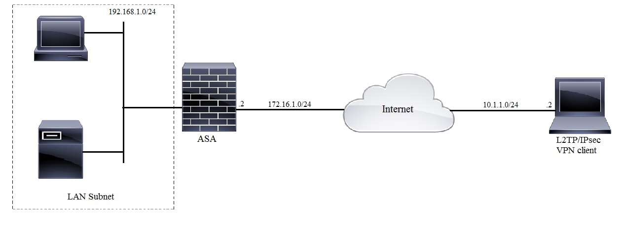
Full Tunnel Configuration
ASA Configuration Using Adaptive Security Device Manager (ASDM)
Complete these steps:
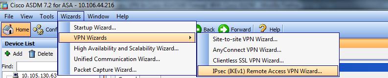
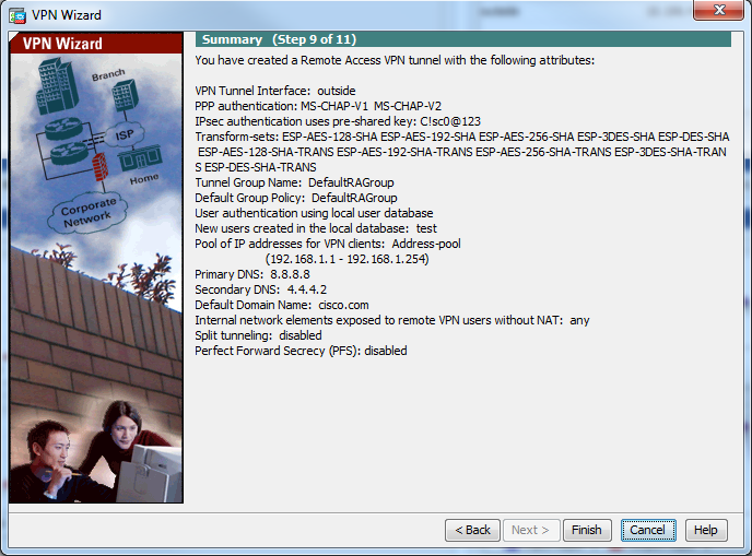
Step 1. Log in to the ASDM, and navigate to Wizards > VPN Wizards > Ipsec (IKEv1) Remote Access VPN Wizard.
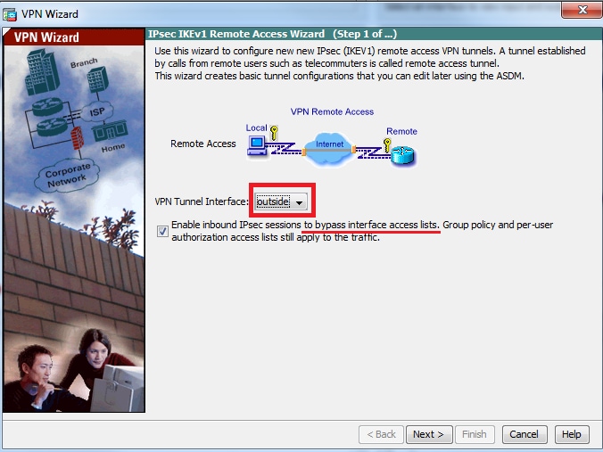
Step 2. A Remote Access VPN setup window appears. From the drop-down list, choose the interface on which VPN tunnel has to be terminated. In this example outside interface is connected to WAN and so terminating VPN tunnels on this interface. Keep the box Enable inbound IPSec sessions to bypass interface access lists. Group policy and per-user authorization access lists still apply to the traffic checked so that new access-list need not to be configured on outside interface to allow the clients to access internal resources. Click Next.
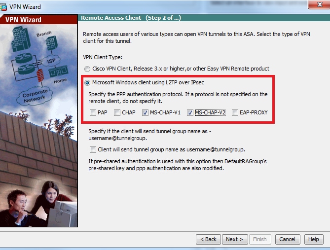
Step 3. As showin in this image, choose the client type as Microsoft Windows client using L2TP over IPSec and MS-CHAP-V1 and MS-CHAP-V2 as PPP authentication protocol since PAP is not secure and other authentication types are not supported with LOCAL database as authentication server and Click Next.
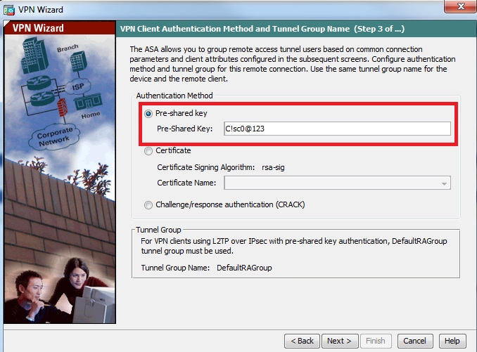
Step 4. Choose the authentication method as Pre-shared-key and type the pre-shared-key which must be same on the client side as well and click Next, as shown in this image.
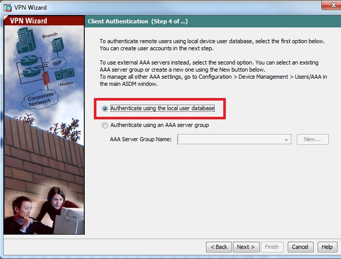
Step 5. Specify a method to authenticate users who attempt L2TP over IPsec connections. Either an external AAA authentication server or its own local database can be used. Choose Authenticate using the local user database if you want to authenticate the clients against local database of ASA and Click Next.
Note: Please refer Configure RADIUS Authentication for VPN users to authenticate the users using external AAA server.
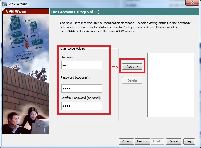
Step 6. To add new users to the local database for user authentication, enter the username and password and then click ADD or else existing user accounts in the database can be used, as shown in this image. Click Next.
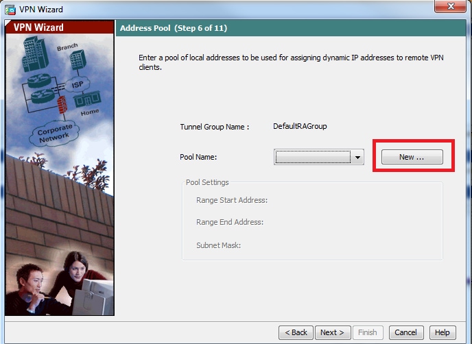
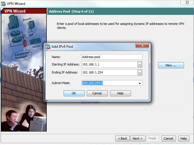
Step 7. From the drop-down list, choose the address pool to be used for assigning IP address to the clients. To create new address pool, click New, as shown in this image.
Step 8. The Add IPv4 Pool dialog box appears.
- Enter the name of the new IP address pool.
- Enter the starting and ending IP addresses.
- Enter the subnet mask and click OK.
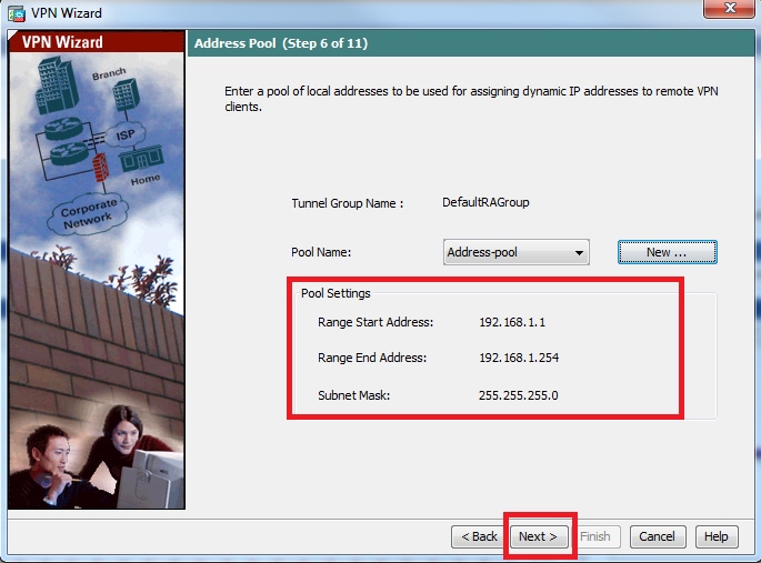
Step 9. Verify the pool settings and click Next.
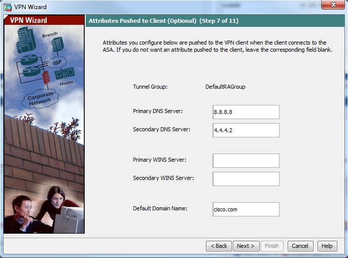
Step 10. Configure the attributes to be pushed to the clients or leave it empty and click Next.
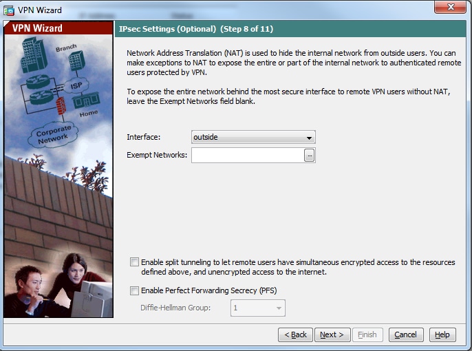
Step 11: Ensure that Enable Perfect Forwarding Secrecy (PFS) box is unchecked as some client platforms do not support this feature. Enable split tunneling to let remote users have simultaneous encrypted access to the resources defined above, and unencrypted access to the internet box is unchecked which means the full tunneling is enabled in which all traffic (including internet traffic) from the client machine will be sent to the ASA over the VPN tunnel. Click Next.
Step 12. Review the summary information and then click Finish.
ASA Configuration Using CLI
Step 1. Configure IKE Phase 1 policy parameters.
This policy is used to protect control traffic between the peers (that is, it protects pre-shared key and phase 2 negotiations)
ciscoasa(config)#crypto ikev1 policy 10
ciscoasa(config-ikev1-policy)#authentication pre-share
ciscoasa(config-ikev1-policy)#encryption 3des
ciscoasa(config-ikev1-policy)#hash sha
ciscoasa(config-ikev1-policy)#group 2
ciscoasa(config-ikev1-policy)#lifetime 86400
ciscoasa(config-ikev1-policy)#exit
[an error occurred while processing this directive]
Step 2. Configure Transform-set.
It contains IKE Phase 2 policy parameters which are used to protect the data traffic. Since the Windows L2TP/IPsec client uses IPsec transport mode, set the mode to transport. The default is tunnel mode
ciscoasa(config)#crypto ipsec ikev1 transform-set TRANS-ESP-3DES-SHA esp-3des esp-sha-hmac
ciscoasa(config)#crypto ipsec ikev1 transform-set TRANS-ESP-3DES-SHA mode transport
[an error occurred while processing this directive]
Step 3. Configure dynamic map.
As windows clients get dynamic IP address fron ISP or local DHCP server (example modem), ASA is not aware about the peer IP address and this poses a problem in the configuration of a static peer on the ASA end. So dynamic crypto configuration has to be approached in which all the parameters are not necessarily defined and the missing parameters are later dynamically learned, as the result of IPSec negotiation from the client.
ciscoasa(config)#crypto dynamic-map outside_dyn_map 10 set ikev1 transform-set TRANS-ESP-3DES-SHA
[an error occurred while processing this directive]
Step 4. Bind dynamic map to static crypto map and apply the crypto map and enable IKEv1 on outside interface
Dynamic crypto map cannot be applied on an interface and so bind it to static crypto map. Dynamic crypto sets should be the lowest priority crypto maps in the crypto map set (that is, they should have the highest sequence numbers) so that the ASA evaluates other crypto maps first. It examines the dynamic crypto map set only when the other (static) map entries do not match.
ciscoasa(config)#crypto map outside_map 65535 ipsec-isakmp dynamic outside_dyn_map
ciscoasa(config)#crypto map outside_map interface outside
ciscoasa(config)#crypto ikev1 enable outside
[an error occurred while processing this directive]
Step 5. Create IP address pool
Create a pool of addresses from which IP addresses are assigned dynamically to the remote VPN Clients. Ignore this step to use existing pool on ASA.
ciscoasa(config)#ip local pool Address-pool 192.168.1.1-192.168.1.254 mask 255.255.255.0
[an error occurred while processing this directive]
Step 6. Configure group-policy
Identify the group policy as internal which means the attributes is pulled from local database.
ciscoasa(config)#group-policy L2TP-VPN internal
[an error occurred while processing this directive]
Note: L2TP/IPsec connections can be configured with either default group policy (DfltGrpPolicy) or a user-defined group policy. In either case, the group policy must be configured to use the L2TP/IPsec tunneling protocol. configure l2tp-ipsec on the VPN protocol attribute on the default group-policy which will get inherited to the user-defined group policy if the vpn-protocol attribute is not configured on it.
Configure the attributes such as vpn tunnel protocol (in our case, it is l2tp-ipsec), domain name, DNS and WINS server IP address and new user accounts
ciscoasa(config)#group-policy L2TP-VPN attributes
ciscoasa(config-group-policy)#dns-server value 8.8.8.8 4.4.4.2
ciscoasa(config-group-policy)#vpn-tunnel-protocol l2tp-ipsec
ciscoasa(config-group-policy)#default-domain value cisco.com
[an error occurred while processing this directive]
Configure usernames and passwords on the device in addition to using AAA. If the user is an L2TP client that uses Microsoft CHAP version 1 or version 2, and the ASA is configured to authenticate against the local database, mschap keyword must be included. For example, username <username> password <password> mschap.
ciscoasa(config-group-policy)# username test password test mschap
[an error occurred while processing this directive]
Step 7. Configure tunnel-group
Create a tunnel group with the tunnel-group command, and specify the local address pool name used to allocate the IP address to the client. If authentication method is pre-shared-key, tunnel group name must be DefaultRAGroup as there is no option on the client to specify the tunnel group and so it lands on default tunnel-group only. Bind the group policy to tunnel-group using the default-group-policy command
ciscoasa(config)#tunnel-group DefaultRAGroup general-attributes
ciscoasa(config-tunnel-general)#address-pool Address-pool
ciscoasa(config-tunnel-general)#default-group-policy L2TP-VPN
ciscoasa(config-tunnel-general)#exit
[an error occurred while processing this directive]
Note: The default connection profile (tunnel group), DefaultRAGroup has to be configured, if pre-shared key based authentication is performed. If certificate-based authentication is performed, a user-defined connection profile can be chosen based on certificate identifiers
Use the tunnel-group ipsec-attributes command to enter the ipsec-attribute configuration mode in order to set the pre-shared key.
ciscoasa(config)# tunnel-group DefaultRAGroup ipsec-attributes
ciscoasa(config-tunnel-ipsec)#  ikev1 pre-shared-key C!sc0@123
ciscoasa(config-tunnel-ipsec)#exit
[an error occurred while processing this directive]
Configure the PPP authentication protocol with the authentication type command from tunnel group ppp-attributes mode. Disable CHAP which is enabled by default as it is not supported if AAA server is configured as local database.
ciscoasa(config)#tunnel-group DefaultRAGroup ppp-attributes
ciscoasa(config-ppp)#no authentication chap
ciscoasa(config-ppp)#authentication ms-chap-v2
ciscoasa(config-ppp)#exit
[an error occurred while processing this directive]
Step 8. Configure NAT-Exemption
Configure NAT-Exemption so that the clients can access internal resources connected to internal interfaces (In this example, internal resources are connected to inside interface).
ciscoasa(config)#object network L2TP-Pool
ciscoasa(config-network-object)#subnet 192.168.1.0 255.255.255.0
ciscoasa(config-network-object)#exit
ciscoasa(config)# nat (inside,outside) source static any any destination static L2TP-Pool L2TP-Pool no-proxy-arp route-lookup
[an error occurred while processing this directive]
Complete Sample Configuration
crypto ikev1 policy 10
authentication pre-share
encryption 3des
hash sha
group 2
lifetime 86400
exitcrypto ipsec ikev1 transform-set TRANS-ESP-3DES-SHA esp-3des esp-sha-hmac
crypto ipsec ikev1 transform-set TRANS-ESP-3DES-SHA mode transportcrypto dynamic-map outside_dyn_map 10 set ikev1 transform-set TRANS-ESP-3DES-SHA
crypto map outside_map 65535 ipsec-isakmp dynamic outside_dyn_map
crypto map outside_map interface outside
crypto ikev1 enable outsideip local pool Address-pool 192.168.1.1-192.168.1.254 mask 255.255.255.0
group-policy L2TP-VPN internal
group-policy L2TP-VPN attributes
vpn-tunnel-protocol l2tp-ipsec
default-domain value cisco.com
username test password test mschap
exittunnel-group DefaultRAGroup general-attributes
address-pool Address-pool
default-group-policy L2TP-VPN
exittunnel-group DefaultRAGroup ipsec-attributes
ikev1 pre-shared-key C!sc0@123
exittunnel-group DefaultRAGroup ppp-attributes
no authentication chap
authentication ms-chap-v2
exitobject network L2TP-Pool
subnet 192.168.1.0 255.255.255.0
exit
nat(inside,outside) source static any any destination static L2TP-Pool L2TP-Pool no-proxy-arp route-lookup
[an error occurred while processing this directive]
Windows 8 L2TP/IPsec Client Configuration
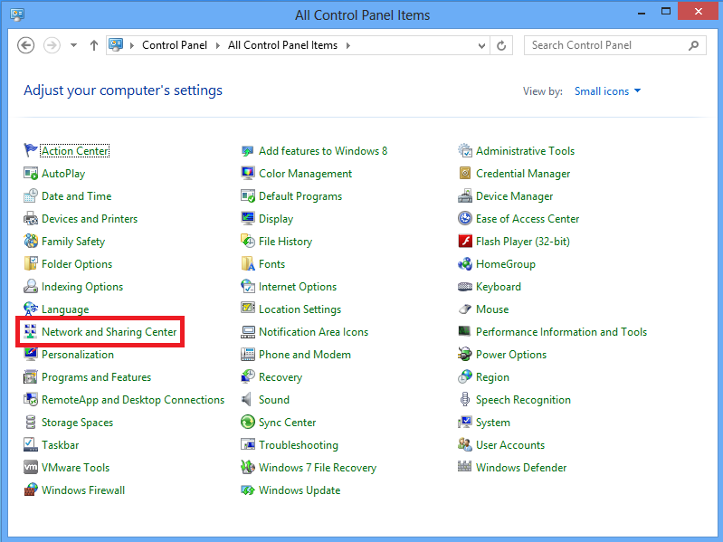
1. Open Control panel and select Network and Sharing center.
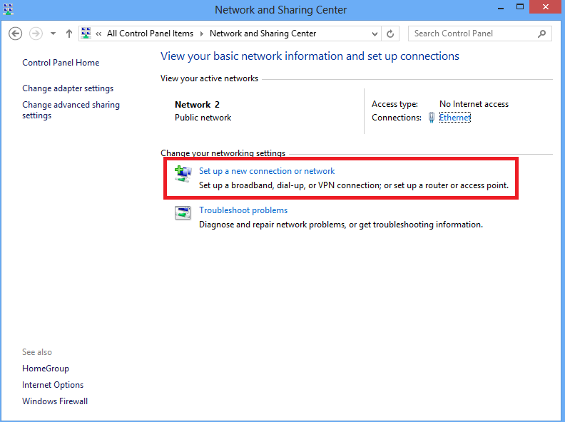
2. Choose Set up a new connection or network option.
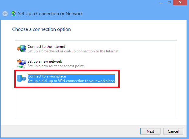
3. Choose Connect to a workplace option and click Next.
4.Click Use my Internet connection (VPN) option.
5. Enter IP address of ASA’s WAN interface or FQDN and any name for VPN adapter which is locally significant and click Create.
6. On Network and Sharing Center, choose Change adapter settings option on the left pane of the window.
7. Right click the recently created adapterfor L2TP VPN and choose Properties.
8. Navigate to Security tab, choose the Type of VPN as Layer 2 Tunneling Protocol with IPsec (L2TP/IPsec) and then click on Advanced settings.
9. Enter the preshared key as the same mentioned in tunnel-group DefaultRAGroup and click OK. In this example, C!sc0@123 is used as the pre-shared key.
10. Choose the authentication method as Allow these protocols and ensure that only «Microsoft CHAP Version 2 (MS-CHAP v2) checkbox is checked and click OK.
11. Under network connections, right click on L2TP VPN adapter and choose Connect/Disconnect.
12. Networks icon will pop up and click Connect on L2TP VPN connection.
13. Enter the user credentials and click OK.
If the required parameters are matched on both the ends, L2TP/IPsec connection will be established.
Split Tunnel Configuration
Split tunnelling is a feature that you can use in order to define the traffic for the subnets or hosts that must be encrypted. This involves the configuration of an Access Control List (ACL) that is associated with this feature. The traffic for the subnets or hosts that is defined on this ACL gets encrypted over the tunnel from the client-end, and the routes for these subnets are installed on the PC routing table. ASA intercepts DHCPINFORM message from a client and responds with the subnet mask, domain name, and classless static routes.
Configuration on ASA
ciscoasa(config)# access-list SPLIT standard permit 10.1.1.0 255.255.255.0ciscoasa(config)# group-policy DefaultRAGroup attributes
ciscoasa(config-group-policy)# split-tunnel-policy tunnelspecified
ciscoasa(config-group-policy)# split-tunnel-network-list value SPLIT
ciscoasa(config-group-policy)# intercept-dhcp 255.255.255.255 enable
[an error occurred while processing this directive]
Configuration on L2TP/IPsec client
1. Right click on the L2TP VPN adapter and choose Properties.

2. Navigate to Networking tab, choose Internet Protocol Version 4 (TCP/IPv4) and then click on Properties.
3. Click Advanced option.
4. Uncheck Use default gateway on remote network option and click OK.
Verify
Use this section in order to confirm that your configuration works properly.
Note: The Output Interpreter Tool (registered customers only) supports certain show commands. Use the Output Interpreter Tool in order to view an analysis of show command output.
- show crypto ikev1 sa — Shows all current IKE SAs at a peer.
ciscoasa# show crypto ikev1 saIKEv1 SAs:   Active SA: 1
    Rekey SA: 0 (A tunnel will report 1 Active and 1 Rekey SA during rekey)
Total IKE SA: 11   IKE Peer:
10.1.1.2
    Type    : user            Role    : responder
    Rekey   : no
State : MM_ACTIVE
[an error occurred while processing this directive]
- show crypto ipsec sa — Shows all current IPsec SAs at a peer.
ciscoasa# show crypto ipsec sa
interface: outside
    Crypto map tag:
outside_dyn_map
, seq num: 10, local addr: 172.16.1.2local ident (addr/mask/prot/port): (172.16.1.2/255.255.255.255/
17/1701
)
      remote ident (addr/mask/prot/port): (10.1.1.2/255.255.255.255/
17/1701
)
current_peer: 10.1.1.2, username: test
dynamic allocated peer ip: 192.168.1.1
dynamic allocated peer ip(ipv6): 0.0.0.0
#pkts encaps: 29, #pkts encrypt: 29, #pkts digest: 29
#pkts decaps: 118, #pkts decrypt: 118, #pkts verify: 118
#pkts compressed: 0, #pkts decompressed: 0
#pkts not compressed: 29, #pkts comp failed: 0, #pkts decomp failed: 0
#post-frag successes: 0, #post-frag failures: 0, #fragments created: 0
#PMTUs sent: 0, #PMTUs rcvd: 0, #decapsulated frgs needing reassembly: 0
#TFC rcvd: 0, #TFC sent: 0
#Valid ICMP Errors rcvd: 0, #Invalid ICMP Errors rcvd: 0
#send errors: 0, #recv errors: 0local crypto endpt.: 172.16.1.2/0, remote crypto endpt.: 10.1.1.2/0
path mtu 1500, ipsec overhead 58(36), media mtu 1500
PMTU time remaining (sec): 0, DF policy: copy-df
ICMP error validation: disabled, TFC packets: disabled
current outbound spi: E8AF927A
current inbound spi : 71F346ABinbound esp sas:
spi: 0x71F346AB (1911768747)
transform: esp-3des esp-sha-hmac no compression
in use settings ={RA, Transport, IKEv1, }
slot: 0, conn_id: 4096, crypto-map: outside_dyn_map
sa timing: remaining key lifetime (kB/sec): (237303/3541)
IV size: 8 bytes
replay detection support: Y
Anti replay bitmap:
0x00000000 0x00000003
outbound esp sas:
spi: 0xE8AF927A (3903820410)
transform: esp-3des esp-sha-hmac no compression
in use settings ={RA, Transport, IKEv1, }
slot: 0, conn_id: 4096, crypto-map: outside_dyn_map
sa timing: remaining key lifetime (kB/sec): (237303/3541)
IV size: 8 bytes
replay detection support: Y
Anti replay bitmap:
0x00000000 0x00000001
[an error occurred while processing this directive]
- show vpn-sessiondb detail ra-ikev1-ipsec filter protocol l2tpOverIpSec — Shows detailed information about L2TP over IPsec connections.
ciscoasa# show vpn-sessiondb detail ra-ikev1-ipsec filter protocol l2tpOverIpSecSession Type: IKEv1 IPsec Detailed
Username : test
Index : 1
Assigned IP : 192.168.1.1 Public IP : 10.1.1.2
Protocol     : IKEv1 IPsec L2TPOverIPsec
License      : Other VPN
Encryption   : IKEv1: (1)3DES  IPsec: (1)3DES  L2TPOverIPsec: (1)none
Hashing      : IKEv1: (1)SHA1  IPsec: (1)SHA1  L2TPOverIPsec: (1)none
Bytes Tx     : 1574                   Bytes Rx     : 12752
Pkts Tx      : 29                     Pkts Rx      : 118
Pkts Tx Drop : 0                      Pkts Rx Drop : 0
Group Policy : L2TP-VPN Tunnel Group : DefaultRAGroup
Login Time   : 23:32:48 UTC Sat May 16 2015
Duration     : 0h:04m:05s
Inactivity   : 0h:00m:00s
VLAN Mapping : N/A                    VLAN         : none
Audt Sess ID : 0a6a2577000010005557d3a0
Security Grp : noneIKEv1 Tunnels: 1
IPsec Tunnels: 1
L2TPOverIPsec Tunnels: 1
IKEv1:
  Tunnel ID    : 1.1
  UDP Src Port : 500                    UDP Dst Port : 500
  IKE Neg Mode : Main                   Auth Mode    : preSharedKeys
  Encryption   : 3DES                   Hashing      : SHA1
  Rekey Int (T): 28800 Seconds          Rekey Left(T): 28555 Seconds
  D/H Group    : 2
  Filter Name  :
IPsec:
  Tunnel ID    : 1.2
  Local Addr   : 172.16.1.2/255.255.255.255/17/1701
  Remote Addr  : 10.1.1.2/255.255.255.255/17/1701
  Encryption   : 3DES                   Hashing      : SHA1
  Encapsulation: Transport
  Rekey Int (T): 3600 Seconds           Rekey Left(T): 3576 Seconds
  Rekey Int (D): 250000 K-Bytes         Rekey Left(D): 250000 K-Bytes
  Idle Time Out: 30 Minutes             Idle TO Left : 29 Minutes
  Bytes Tx     : 1574                   Bytes Rx     : 12752
  Pkts Tx      : 29                     Pkts Rx      : 118
L2TPOverIPsec:
Tunnel ID : 1.3
Username : test
Assigned IP : 192.168.1.1
Public IP : 10.1.1.2
Encryption : none Hashing : none
Auth Mode : msCHAPV2
  Idle Time Out: 30 Minutes             Idle TO Left : 27 Minutes
  Client OS    : Microsoft
  Client OS Ver: 6.2
  Bytes Tx     : 475                    Bytes Rx     : 9093
  Pkts Tx      : 18                     Pkts Rx      : 105
[an error occurred while processing this directive]
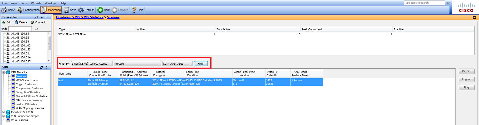
On ASDM, under Monitoring > VPN > VPN Statistics > Sessions the general information regarding the VPN session can be seen. L2TP over IPsec sessions can be filtered by IPsec (IKEv1) Remote Access > Protocol > L2TP Over IPsec.
Troubleshoot
This section provides information you can use in order to troubleshoot your configuration.
Note: Refer to Important Information on Debug Commands before you use debug commands.
Caution: On the ASA, you can set various debug levels; by default, level 1 is used. If you change the debug level, the verbosity of the debugs might increase. Do this with caution, especially in production environments!
Use the following debug commands with caution in order to troubleshoot the problems with VPN tunnel
- debug crypto ikev1 — displays debug information about IKE
- debug crypto ipsec — displays debug information about IPsec
Here is the debug output for a successful L2TP over IPSec connection:
May 18 04:17:18 [IKEv1]IKE Receiver: Packet received on 172.16.1.2:500 from 10.1.1.2:500
May 18 04:17:18 [IKEv1]IP = 10.1.1.2, IKE_DECODE RECEIVED Message (msgid=0) with payloads : HDR + SA (1) + VENDOR (13) + VENDOR (13) + VENDOR (13) + VENDOR (13) + VENDOR (13) + VENDOR (13) + VENDOR (13) + VENDOR (13) + NONE (0) total length : 408
May 18 04:17:18 [IKEv1 DEBUG]IP = 10.1.1.2, processing SA payload
May 18 04:17:18 [IKEv1]Phase 1 failure:  Mismatched attribute types for class Group Description:  Rcv'd: Unknown  Cfg'd: Group 2
May 18 04:17:18 [IKEv1]Phase 1 failure:  Mismatched attribute types for class Group Description:  Rcv'd: Unknown  Cfg'd: Group 2
May 18 04:17:18 [IKEv1 DEBUG]IP = 10.1.1.2, Oakley proposal is acceptable
May 18 04:17:18 [IKEv1 DEBUG]IP = 10.1.1.2, processing VID payload
May 18 04:17:18 [IKEv1 DEBUG]IP = 10.1.1.2, processing VID payload
May 18 04:17:18 [IKEv1 DEBUG]IP = 10.1.1.2, processing VID payload
May 18 04:17:18 [IKEv1 DEBUG]IP = 10.1.1.2, Received NAT-Traversal RFC VID
May 18 04:17:18 [IKEv1 DEBUG]IP = 10.1.1.2, processing VID payload
May 18 04:17:18 [IKEv1 DEBUG]IP = 10.1.1.2, Received NAT-Traversal ver 02 VID
May 18 04:17:18 [IKEv1 DEBUG]IP = 10.1.1.2, processing VID payload
May 18 04:17:18 [IKEv1 DEBUG]IP = 10.1.1.2, Received Fragmentation VID
May 18 04:17:18 [IKEv1 DEBUG]IP = 10.1.1.2, processing VID payload
May 18 04:17:18 [IKEv1 DEBUG]IP = 10.1.1.2, processing VID payload
May 18 04:17:18 [IKEv1 DEBUG]IP = 10.1.1.2, processing VID payload
May 18 04:17:18 [IKEv1 DEBUG]IP = 10.1.1.2, processing IKE SA payload
May 18 04:17:18 [IKEv1]Phase 1 failure:  Mismatched attribute types for class Group Description:  Rcv'd: Unknown  Cfg'd: Group 2
May 18 04:17:18 [IKEv1]Phase 1 failure:  Mismatched attribute types for class Group Description:  Rcv'd: Unknown  Cfg'd: Group 2
May 18 04:17:18 [IKEv1 DEBUG]IP = 10.1.1.2,
IKE SA Proposal # 1, Transform # 5 acceptable Matches global IKE entry # 2
May 18 04:17:18 [IKEv1 DEBUG]IP = 10.1.1.2, constructing ISAKMP SA payload
May 18 04:17:18 [IKEv1 DEBUG]IP = 10.1.1.2, constructing NAT-Traversal VID ver RFC payload
May 18 04:17:18 [IKEv1 DEBUG]IP = 10.1.1.2, constructing Fragmentation VID + extended capabilities payload
May 18 04:17:18 [IKEv1]IP = 10.1.1.2, IKE_DECODE SENDING Message (msgid=0) with payloads : HDR + SA (1) + VENDOR (13) + VENDOR (13) + NONE (0) total length : 124
May 18 04:17:18 [IKEv1]IKE Receiver: Packet received on 172.16.1.2:500 from 10.1.1.2:500
May 18 04:17:18 [IKEv1]IP = 10.1.1.2, IKE_DECODE RECEIVED Message (msgid=0) with payloads : HDR + KE (4) + NONCE (10) + NAT-D (20) + NAT-D (20) + NONE (0) total length : 260
May 18 04:17:18 [IKEv1 DEBUG]IP = 10.1.1.2, processing ke payload
May 18 04:17:18 [IKEv1 DEBUG]IP = 10.1.1.2, processing ISA_KE payload
May 18 04:17:18 [IKEv1 DEBUG]IP = 10.1.1.2, processing nonce payload
May 18 04:17:18 [IKEv1 DEBUG]IP = 10.1.1.2, processing NAT-Discovery payload
May 18 04:17:18 [IKEv1 DEBUG]IP = 10.1.1.2, computing NAT Discovery hash
May 18 04:17:18 [IKEv1 DEBUG]IP = 10.1.1.2, processing NAT-Discovery payload
May 18 04:17:18 [IKEv1 DEBUG]IP = 10.1.1.2, computing NAT Discovery hash
May 18 04:17:18 [IKEv1 DEBUG]IP = 10.1.1.2, constructing ke payload
May 18 04:17:18 [IKEv1 DEBUG]IP = 10.1.1.2, constructing nonce payload
May 18 04:17:18 [IKEv1 DEBUG]IP = 10.1.1.2, constructing Cisco Unity VID payload
May 18 04:17:18 [IKEv1 DEBUG]IP = 10.1.1.2, constructing xauth V6 VID payload
May 18 04:17:18 [IKEv1 DEBUG]IP = 10.1.1.2, Send IOS VID
May 18 04:17:18 [IKEv1 DEBUG]IP = 10.1.1.2, Constructing ASA spoofing IOS Vendor ID payload (version: 1.0.0, capabilities: 20000001)
May 18 04:17:18 [IKEv1 DEBUG]IP = 10.1.1.2, constructing VID payload
May 18 04:17:18 [IKEv1 DEBUG]IP = 10.1.1.2, Send Altiga/Cisco VPN3000/Cisco ASA GW VID
May 18 04:17:18 [IKEv1 DEBUG]IP = 10.1.1.2, constructing NAT-Discovery payload
May 18 04:17:18 [IKEv1 DEBUG]IP = 10.1.1.2, computing NAT Discovery hash
May 18 04:17:18 [IKEv1 DEBUG]IP = 10.1.1.2, constructing NAT-Discovery payload
May 18 04:17:18 [IKEv1 DEBUG]IP = 10.1.1.2, computing NAT Discovery hash
May 18 04:17:18 [IKEv1]IP = 10.1.1.2,
Connection landed on tunnel_group DefaultRAGroup
May 18 04:17:18 [IKEv1 DEBUG]Group = DefaultRAGroup, IP = 10.1.1.2, Generating keys for Responder...
May 18 04:17:18 [IKEv1]IP = 10.1.1.2, IKE_DECODE SENDING Message (msgid=0) with payloads : HDR + KE (4) + NONCE (10) + VENDOR (13) + VENDOR (13) + VENDOR (13) + VENDOR (13) + NAT-D (20) + NAT-D (20) + NONE (0) total length : 304
May 18 04:17:18 [IKEv1]IKE Receiver: Packet received on 172.16.1.2:500 from 10.1.1.2:500
May 18 04:17:18 [IKEv1]IP = 10.1.1.2, IKE_DECODE RECEIVED Message (msgid=0) with payloads : HDR + ID (5) + HASH (8) + NONE (0) total length : 64
May 18 04:17:18 [IKEv1 DEBUG]Group = DefaultRAGroup, IP = 10.1.1.2, processing ID payload
May 18 04:17:18 [IKEv1 DECODE]Group = DefaultRAGroup, IP = 10.1.1.2, ID_IPV4_ADDR ID received
10.1.1.2
May 18 04:17:18 [IKEv1 DEBUG]Group = DefaultRAGroup, IP = 10.1.1.2, processing hash payload
May 18 04:17:18 [IKEv1 DEBUG]Group = DefaultRAGroup, IP = 10.1.1.2, Computing hash for ISAKMP
May 18 04:17:18 [IKEv1]Group = DefaultRAGroup, IP = 10.1.1.2,
Automatic NAT Detection Status: Remote end is NOT behind a NAT device This end is NOT behind a NAT device
May 18 04:17:18 [IKEv1]IP = 10.1.1.2, Connection landed on tunnel_group DefaultRAGroup
May 18 04:17:18 [IKEv1 DEBUG]Group = DefaultRAGroup, IP = 10.1.1.2, constructing ID payload
May 18 04:17:18 [IKEv1 DEBUG]Group = DefaultRAGroup, IP = 10.1.1.2, constructing hash payload
May 18 04:17:18 [IKEv1 DEBUG]Group = DefaultRAGroup, IP = 10.1.1.2, Computing hash for ISAKMP
May 18 04:17:18 [IKEv1 DEBUG]Group = DefaultRAGroup, IP = 10.1.1.2, constructing dpd vid payload
May 18 04:17:18 [IKEv1]IP = 10.1.1.2, IKE_DECODE SENDING Message (msgid=0) with payloads : HDR + ID (5) + HASH (8) + VENDOR (13) + NONE (0) total length : 84
May 18 04:17:18 [IKEv1]Group = DefaultRAGroup, IP = 10.1.1.2,
PHASE 1 COMPLETED
May 18 04:17:18 [IKEv1]IP = 10.1.1.2, Keep-alive type for this connection: None
May 18 04:17:18 [IKEv1]IP = 10.1.1.2, Keep-alives configured on but peer does not support keep-alives (type = None)
May 18 04:17:18 [IKEv1 DEBUG]Group = DefaultRAGroup, IP = 10.1.1.2, Starting P1 rekey timer: 21600 seconds.
May 18 04:17:18 [IKEv1]IKE Receiver: Packet received on 172.16.1.2:500 from 10.1.1.2:500
May 18 04:17:18 [IKEv1 DECODE]IP = 10.1.1.2, IKE Responder starting QM: msg id = 00000001
May 18 04:17:18 [IKEv1]IP = 10.1.1.2, IKE_DECODE RECEIVED Message (msgid=1) with payloads : HDR + HASH (8) + SA (1) + NONCE (10) + ID (5) + ID (5) + NONE (0) total length : 300
May 18 04:17:18 [IKEv1 DEBUG]Group = DefaultRAGroup, IP = 10.1.1.2, processing hash payload
May 18 04:17:18 [IKEv1 DEBUG]Group = DefaultRAGroup, IP = 10.1.1.2, processing SA payload
May 18 04:17:18 [IKEv1 DEBUG]Group = DefaultRAGroup, IP = 10.1.1.2, processing nonce payload
May 18 04:17:18 [IKEv1 DEBUG]Group = DefaultRAGroup, IP = 10.1.1.2, processing ID payload
May 18 04:17:18 [IKEv1 DECODE]Group = DefaultRAGroup, IP = 10.1.1.2, ID_IPV4_ADDR ID received
10.1.1.2
May 18 04:17:18 [IKEv1]Group = DefaultRAGroup, IP = 10.1.1.2,
Received remote Proxy Host data in ID Payload: Address 10.1.1.2, Protocol 17, Port 1701
May 18 04:17:18 [IKEv1 DEBUG]Group = DefaultRAGroup, IP = 10.1.1.2, processing ID payload
May 18 04:17:18 [IKEv1 DECODE]Group = DefaultRAGroup, IP = 10.1.1.2, ID_IPV4_ADDR ID received
172.16.1.2
May 18 04:17:18 [IKEv1]Group = DefaultRAGroup, IP = 10.1.1.2,
Received local Proxy Host data in ID Payload: Address 172.16.1.2, Protocol 17, Port 1701
May 18 04:17:18 [IKEv1]Group = DefaultRAGroup, IP = 10.1.1.2,
L2TP/IPSec session detected.
May 18 04:17:18 [IKEv1]Group = DefaultRAGroup, IP = 10.1.1.2, QM IsRekeyed old sa not found by addr
May 18 04:17:18 [IKEv1]Group = DefaultRAGroup, IP = 10.1.1.2,
Static Crypto Map check, map outside_dyn_map, seq = 10 is a successful match
May 18 04:17:18 [IKEv1]Group = DefaultRAGroup, IP = 10.1.1.2, IKE Remote Peer configured for crypto map: outside_dyn_map
May 18 04:17:18 [IKEv1 DEBUG]Group = DefaultRAGroup, IP = 10.1.1.2, processing IPSec SA payload
May 18 04:17:18 [IKEv1 DEBUG]Group = DefaultRAGroup, IP = 10.1.1.2, I
PSec SA Proposal # 2, Transform # 1 acceptable
  Matches global IPSec SA entry # 10
May 18 04:17:18 [IKEv1]Group = DefaultRAGroup, IP = 10.1.1.2, IKE: requesting SPI!
IPSEC: New embryonic SA created @ 0x00007fffe13ab260,
    SCB: 0xE1C00540,
    Direction: inbound
    SPI      : 0x7AD72E0D
    Session ID: 0x00001000
    VPIF num  : 0x00000002
    Tunnel type: ra
    Protocol   : esp
    Lifetime   : 240 seconds
May 18 04:17:18 [IKEv1 DEBUG]Group = DefaultRAGroup, IP = 10.1.1.2, IKE got SPI from key engine: SPI = 0x7ad72e0d
May 18 04:17:18 [IKEv1 DEBUG]Group = DefaultRAGroup, IP = 10.1.1.2, oakley constucting quick mode
May 18 04:17:18 [IKEv1 DEBUG]Group = DefaultRAGroup, IP = 10.1.1.2, constructing blank hash payload
May 18 04:17:18 [IKEv1 DEBUG]Group = DefaultRAGroup, IP = 10.1.1.2, constructing IPSec SA payload
May 18 04:17:18 [IKEv1 DEBUG]Group = DefaultRAGroup, IP = 10.1.1.2, constructing IPSec nonce payload
May 18 04:17:18 [IKEv1 DEBUG]Group = DefaultRAGroup, IP = 10.1.1.2, constructing proxy ID
May 18 04:17:18 [IKEv1 DEBUG]Group = DefaultRAGroup, IP = 10.1.1.2,
Transmitting Proxy Id:
Remote host: 10.1.1.2 Protocol 17 Port 1701
Local host: 172.16.1.2 Protocol 17 Port 1701
May 18 04:17:18 [IKEv1 DEBUG]Group = DefaultRAGroup, IP = 10.1.1.2, constructing qm hash payload
May 18 04:17:18 [IKEv1 DECODE]Group = DefaultRAGroup, IP = 10.1.1.2, IKE Responder sending 2nd QM pkt: msg id = 00000001
May 18 04:17:18 [IKEv1]IP = 10.1.1.2, IKE_DECODE SENDING Message (msgid=1) with payloads : HDR + HASH (8) + SA (1) + NONCE (10) + ID (5) + ID (5) + NONE (0) total length : 160
May 18 04:17:18 [IKEv1]IKE Receiver: Packet received on 172.16.1.2:500 from 10.1.1.2:500
May 18 04:17:18 [IKEv1]IP = 10.1.1.2, IKE_DECODE RECEIVED Message (msgid=1) with payloads : HDR + HASH (8) + NONE (0) total length : 52
May 18 04:17:18 [IKEv1 DEBUG]Group = DefaultRAGroup, IP = 10.1.1.2, processing hash payload
May 18 04:17:18 [IKEv1 DEBUG]Group = DefaultRAGroup, IP = 10.1.1.2, loading all IPSEC SAs
May 18 04:17:18 [IKEv1 DEBUG]Group = DefaultRAGroup, IP = 10.1.1.2, Generating Quick Mode Key!
May 18 04:17:18 [IKEv1 DEBUG]Group = DefaultRAGroup, IP = 10.1.1.2, NP encrypt rule look up for crypto map outside_dyn_map 10 matching ACL Unknown: returned cs_id=e148a8b0; encrypt_rule=00000000; tunnelFlow_rule=00000000
May 18 04:17:18 [IKEv1 DEBUG]Group = DefaultRAGroup, IP = 10.1.1.2, Generating Quick Mode Key!
IPSEC: New embryonic SA created @ 0x00007fffe1c75c00,
    SCB: 0xE13ABD20,
    Direction: outbound
    SPI      : 0x8C14FD70
    Session ID: 0x00001000
    VPIF num  : 0x00000002
    Tunnel type: ra
    Protocol   : esp
    Lifetime   : 240 seconds
IPSEC: Completed host OBSA update, SPI 0x8C14FD70
IPSEC: Creating outbound VPN context, SPI 0x8C14FD70
    Flags: 0x00000205
    SA   : 0x00007fffe1c75c00
    SPI  : 0x8C14FD70
    MTU  : 1500 bytes
    VCID : 0x00000000
    Peer : 0x00000000
    SCB  : 0x0AC609F9
    Channel: 0x00007fffed817200
IPSEC: Completed outbound VPN context, SPI 0x8C14FD70
    VPN handle: 0x00000000000028d4
IPSEC: New outbound encrypt rule, SPI 0x8C14FD70
    Src addr: 172.16.1.2
    Src mask: 255.255.255.255
    Dst addr: 10.1.1.2
    Dst mask: 255.255.255.255
Src ports
Upper: 1701
Lower: 1701
Op : equal
Dst ports
Upper: 1701
Lower: 1701
Op : equal
Protocol: 17
    Use protocol: true
    SPI: 0x00000000
    Use SPI: false
IPSEC: Completed outbound encrypt rule, SPI 0x8C14FD70
    Rule ID: 0x00007fffe1c763d0
IPSEC: New outbound permit rule, SPI 0x8C14FD70
    Src addr: 172.16.1.2
    Src mask: 255.255.255.255
    Dst addr: 10.1.1.2
    Dst mask: 255.255.255.255
    Src ports
      Upper: 0
      Lower: 0
      Op   : ignore
    Dst ports
      Upper: 0
      Lower: 0
      Op   : ignore
    Protocol: 50
    Use protocol: true
    SPI: 0x8C14FD70
    Use SPI: true
IPSEC: Completed outbound permit rule, SPI 0x8C14FD70
    Rule ID: 0x00007fffe1c76a00
May 18 04:17:18 [IKEv1 DEBUG]Group = DefaultRAGroup, IP = 10.1.1.2, NP encrypt rule look up for crypto map outside_dyn_map 10 matching ACL Unknown: returned cs_id=e148a8b0; encrypt_rule=00000000; tunnelFlow_rule=00000000
May 18 04:17:18 [IKEv1]Group = DefaultRAGroup, IP = 10.1.1.2, Security negotiation complete for User ()  Responder, Inbound SPI = 0x7ad72e0d, Outbound SPI = 0x8c14fd70
May 18 04:17:18 [IKEv1 DEBUG]Group = DefaultRAGroup, IP = 10.1.1.2, IKE got a KEY_ADD msg for SA: SPI = 0x8c14fd70
IPSEC: New embryonic SA created @ 0x00007fffe13ab260,
    SCB: 0xE1C00540,
    Direction: inbound
    SPI      : 0x7AD72E0D
    Session ID: 0x00001000
    VPIF num  : 0x00000002
    Tunnel type: ra
    Protocol   : esp
    Lifetime   : 240 seconds
IPSEC: Completed host IBSA update, SPI 0x7AD72E0D
IPSEC: Creating inbound VPN context, SPI 0x7AD72E0D
    Flags: 0x00000206
    SA   : 0x00007fffe13ab260
    SPI  : 0x7AD72E0D
    MTU  : 0 bytes
    VCID : 0x00000000
    Peer : 0x000028D4
    SCB  : 0x0AC5BD5B
    Channel: 0x00007fffed817200
IPSEC: Completed inbound VPN context, SPI 0x7AD72E0D
    VPN handle: 0x0000000000004174
IPSEC: Updating outbound VPN context 0x000028D4, SPI 0x8C14FD70
    Flags: 0x00000205
    SA   : 0x00007fffe1c75c00
    SPI  : 0x8C14FD70
    MTU  : 1500 bytes
    VCID : 0x00000000
    Peer : 0x00004174
    SCB  : 0x0AC609F9
    Channel: 0x00007fffed817200
IPSEC: Completed outbound VPN context, SPI 0x8C14FD70
    VPN handle: 0x00000000000028d4
IPSEC: Completed outbound inner rule, SPI 0x8C14FD70
    Rule ID: 0x00007fffe1c763d0
IPSEC: Completed outbound outer SPD rule, SPI 0x8C14FD70
    Rule ID: 0x00007fffe1c76a00
IPSEC: New inbound tunnel flow rule, SPI 0x7AD72E0D
    Src addr: 10.1.1.2
    Src mask: 255.255.255.255
    Dst addr: 172.16.1.2
    Dst mask: 255.255.255.255
    Src ports
      Upper: 1701
      Lower: 1701
      Op   : equal
    Dst ports
      Upper: 1701
      Lower: 1701
      Op   : equal
    Protocol: 17
    Use protocol: true
    SPI: 0x00000000
    Use SPI: false
IPSEC: Completed inbound tunnel flow rule, SPI 0x7AD72E0D
    Rule ID: 0x00007fffe13aba90
IPSEC: New inbound decrypt rule, SPI 0x7AD72E0D
    Src addr: 10.1.1.2
    Src mask: 255.255.255.255
    Dst addr: 172.16.1.2
    Dst mask: 255.255.255.255
    Src ports
      Upper: 0
      Lower: 0
      Op   : ignore
    Dst ports
      Upper: 0
      Lower: 0
      Op   : ignore
    Protocol: 50
    Use protocol: true
    SPI: 0x7AD72E0D
    Use SPI: true
IPSEC: Completed inbound decrypt rule, SPI 0x7AD72E0D
    Rule ID: 0x00007fffe1c77420
IPSEC: New inbound permit rule, SPI 0x7AD72E0D
    Src addr: 10.1.1.2
    Src mask: 255.255.255.255
    Dst addr: 172.16.1.2
    Dst mask: 255.255.255.255
    Src ports
      Upper: 0
      Lower: 0
      Op   : ignore
    Dst ports
      Upper: 0
      Lower: 0
      Op   : ignore
    Protocol: 50
    Use protocol: true
    SPI: 0x7AD72E0D
    Use SPI: true
IPSEC: Completed inbound permit rule, SPI 0x7AD72E0D
    Rule ID: 0x00007fffe13abb80
May 18 04:17:18 [IKEv1 DEBUG]Group = DefaultRAGroup, IP = 10.1.1.2, Pitcher: received KEY_UPDATE, spi 0x7ad72e0d
May 18 04:17:18 [IKEv1 DEBUG]Group = DefaultRAGroup, IP = 10.1.1.2, Starting P2 rekey timer: 3420 seconds.
May 18 04:17:18 [IKEv1]Group = DefaultRAGroup, IP = 10.1.1.2,
PHASE 2 COMPLETED
 (msgid=00000001)
May 18 04:17:18 [IKEv1]IKEQM_Active() Add L2TP classification rules: ip <10.1.1.2> mask <0xFFFFFFFF> port <1701>
May 18 04:17:21 [IKEv1]Group = DefaultRAGroup,
Username = test, IP = 10.1.1.2, Adding static route for client address: 192.168.1.1
[an error occurred while processing this directive]
Some of the commonly seen VPN related errors on Windows client are shown in this table
| Error Code | Possible Solution |
| 691 | Ensure the username and password entered was correct |
| 789,835 | Ensure pre-shared-key configured on client machine was same as on ASA |
| 800 |
1. Make sure that the VPN type is set to «Layer 2 Tunneling Protocol (L2TP)» 2. Ensure pre-shared-key was configured correctly configured |
| 809 | Make sure UDP port 500, 4500 ( in case either client or server is behind NAT device) and ESP traffic was not blocked |
Related Information
- Cisco ASA 5500 Series Adaptive Security Appliances
- Most Common L2L and Remote Access IPsec VPN Troubleshooting Solutions
- Technical Support & Documentation — Cisco Systems
Skip to content
Надо: настроить VPN-подключение к «нашему» серверу.
Дано:
- Адрес сервера: 1.2.3.4
- Тип VPN: L2TP с IPSec (ms chap-2)
- Pre-shared key (PSK): Password
- Логин: mylogin
- Пароль: MoyParol
Шаг 1.
На клавиатуре нажимаем комбинацию клавишей <Win>+<R>

Шаг 2.
Печатаем команду «control» и нажимаем «Ок»
Шаг 3.
Заходим в «Центр управления сетями и общим доступом»
Шаги с 4 по 17.
Покажу в картинках. Тут всё понятно и без особых пояснений.
Шаг 5.
Шаг 6.
Шаг 7.
Шаг 8.
Шаг 9.
Шаг10.
Шаг11.
Шаг12.
Правой кнопкой мыши кликаем по настраиваемому VPN, в контекстном меню выбираем пункт «Свойства».
Шаг13.
Шаг14.
Шаг 15.
Шаг16.
Правой кнопкой мыши кликаем по настраиваемому VPN, в контекстном меню выбираем пункт «Подключить».
Шаг 17.
Шаг 18.
Всё. Мы подключены к VPN и можем работать.
Замечание 1.
Иногда Windows не может установить VPN-подключение если ваш компьютер находится за NAT. Например, за роутером.
Решение.
Нужно внести следующие изменения в реестр Windows
[HKEY_LOCAL_MACHINE\SYSTEM\CurrentControlSet\services\RasMan\Parameters]
«AllowL2TPWeakCrypto»=dword:00000001
«ProhibitIpSec»=dword:00000001
После перезагрузки компьютера вы скорее всего сможете подключиться к VPN.
Замечание 2.
Если в вашей локальной сети и в сети предприятия используются одинаковые сети (например, и дома, и на предприятии сеть вида 192.168.1.х), то при обращении к ресурсам/серверам предприятия у вас могут быть проблемы, которые обычно решаются прописыванием статических маршрутов.
Но это уже совсем другая история… 🙂
PS.
Недавно встретился ещё с одним глюком VPN на Windows. Рещилось следующим твиком реестра
[HKEY_LOCAL_MACHINE\SYSTEM\CurrentControlSet\services\PolicyAgent]
«AssumeUDPEncapsulationContextOnSendRule»=dword:00000002
«UDPEncapsulationContextOnSendRule»=dword:00000002
[HKEY_LOCAL_MACHINE\SYSTEM\CurrentControlSet\Services\RasMan\Parameters]
«AllowL2TPWeakCrypto»=dword:00000001
«ProhibitIPSec»=dword:00000000
Время на прочтение6 мин
Количество просмотров251K
Недавно я озадачился поиском возможности создания шифрованного подключения к своему офису средствами L2TP/IPsec протокола. Задача усложнилась, когда, кроме Windows клиентов, появилась потребность пускать в сеть еще iOS и Android клиентов. В Интернете множество статей как проделать это на Windows Server с «внешним» IP-адресом. Но я хочу предложить сообществу реализацию стандартными средствами Windows 7/8 шифрованного L2TP тоннеля в локальную сеть с популярной, на мой взгляд, топологией.
Структура сети
Маленькая сеть из десяти Windows 7/8 клиентов с выделенным сервером на базе Windows Server 2008 Std (на него пока не обращаем внимание) и с доступом в Интернет средствами простого роутера. Для VPN сервера я выделил одну из машин на Windows 7 Pro. Далее будет описано два способа поднятия L2TP/IPsec сервера на Windows 7 Pro.
Windows 7 L2TP/IPsec AES 128-bit с использованием сертификата
- Первым делом нужно сгенерировать сертификат компьютера и пользователя на VPN сервере.
Для этого воспользуемся бесплатной утилитой Simple Authority.
Устанавливаем, запускаем. Сразу программа предложит сгенерировать сертификат компьютера. Заполняем поля. Хаотично клацаем по клавиатуре, тем самым генерируя случайное число. Вводим пароль (лучше длиннее 8-ми символов, иначе могут быть глюки) Сертификат компьютера (CA) готов. Если пользователь не добавлен, то добавляем. Справа заполняем необходимые поля. Жмем «New certificate». После этого на рабочем столе появится два файла сертификатов с расширениями *.cer и *.p12 - Установим сертификаты на наш VPN сервер.
Для этого делаем Win+R(«Выполнить»), вводим mmc, жмем Enter. Откроется Консоль.
Добавляем оснастку (Файл->Добавить удалить оснастку). Выбираем «Сертификаты». Жмем «Добавить». Выбираем пункт «учетной записи компьютера» при вопросе, где будет управлять эта оснастка сертификатами. Далее, «Личное»->Правой кнопкой мыши->Все задачи->Импорт->Выбираем файл сертификата с расширением *.p12 (именно его). Вводим пароль, ставим галку «Пометить этот ключ как экспортируемый». В категории «Личное» появится два сертификата. Тот сертификат, у которого поля «Кому выдан» и «Кем выдан» одинаковые, нужно перенести в категорию «Доверенные корневые центры сертификации». - Нужно убедиться в отсутствии параметра ProhibitIpSec=1.
Идем в реестр (Win+R -> regedit). Ищем ветку HKLM\System\CurrentControlSet\Services\Rasman\Parameters. Если вышеуказанного параметра там нет или он равен 0, то все хорошо. Иначе, исправляем это. - Создаем входящее подключение.
Идем в «Центр управления сетями и общим доступом»->«Изменение параметров адаптеров». Жмем клавишу Alt, сверху выпадет меню. Далее Файл->«Новое входящее подключение». Выбираем нужных пользователей, ставим галку «Через интернет… VPN». Выбираем нужные протоколы. На TCP/IP v4->Ставим галку «Разрешить доступ к локальной сети» и обязательно устанавливаем пул адресов, выдаваемых клиенту. После создания подключения обязательно откройте его свойства и во вкладке «Пользователи» проверьте наличие галки «Пользователи должны держать пароли в секрете» - Проверим, открылись ли нужные нам порты. Открываем командную строку и командой netstat /a /p udp смотрим, открылись ли UDP 1701 UDP 4500 UDP 500.
Создание клиентского подключения для этого способа
- Установим сертификаты на нашего VPN клиента. Копируем с VPN сервера сертификаты, которые создали ранее. Устанавливаем их точно таким же способом, как и на сервере.
- Создадим VPN подключение. Идем в «Центр управления сетями и общим доступом» -> Настройка нового подключения или сети. Далее «Подключение к рабочему месту» -> Использовать мое подключение к Интернет. Вводим адрес нашего VPN сервера. Подключение готово.
- Настроим наше VPN подключение. Имя пользователя и пароль, думаю, вопросов не вызывают. Во вкладке «Безопасность» выбираем тип VPN L2TP/IPsec и в дополнительных параметрах выбираем «Использовать сертификат» и убираем галку «Проверить атрибуты имени сертификата». Шифрование ставим Обязательное и «Разрешаем следующие протоколы» проверки подлинности: MS-CHAPv2. Далее вкладка Сеть -> TCP/IPv4 свойства -> Дополнительно -> Убираем галку «Использовать основной шлюз».
- Если не поднимается подключение. То на Windows 8 стоит попробовать такой ключ реестра HKLM\SYSTEM\CurrentControlSet\Services\IPsec создаем параметр DWORD с именем AssumeUDPEncapsulationContextOnSendRule и значением 2. Для Windows 7/Vista этот параметр нужно создать в HKLM\SYSTEM\CurrentControlSet\Services\PolicyAgent
Итоги этого способа
Для Windows клиентов это хороший способ реализации L2TP/IPsec, но когда дело доходит до iOS клиентов, задача расширяется. Проблема в том, что iOS могут подключаться по L2TP только с шифрованием по Заранее подготовленной ключевой фразе (Preshared Key), а по сертификату могут подключаться только к Cisco VPN. Второй способ расскажет, как решить эту проблему.
Windows 7 L2TP/IPsec Preshared Key с ESP 3DES шифрованием и контролем целостности
- Вернемся к чудо-параметру ProhibitIpSec=1. Идем в Реестр, в ветку HKLM\System\CurrentControlSet\Services\Rasman\Parameters и создаем там параметр типа DWORD с именем ProhibitIpSec и присваиваем ему значение 1. После этого необходимо или перезагрузить ОС, или перезапустить службы RemoteAccess и RasMan. Этим действием мы отключаем локальную политику IP безопасности по-умолчанию для IPsec.
- Создадим теперь новую политику безопасности IP. «Выполнить» -> mmc -> Добавить оснастку -> «Управление политикой IP-безопасности» и выбираем Локальный компьютер. Далее «Создать политику IP-безопасности». «Далее» -> Вводим имя -> Галку «Использовать правило по умолчанию» не ставим -> Далее -> «Изменить свойства» галку оставляем. Откроются свойства новой политики. Здесь убрать галку «использовать мастер» и «Добавить». Теперь по порядку о каждой вкладке:
- Список IP-фильтров. Вводим имя, снимаем галку «Исп. мастер», «Добавить». Адрес источника: «Любой». Адрес назначения: «Любой». Вкладка протокол. В выпадающем списке выбираем UDP. Пакеты ИЗ этого порта: 1701. Пакеты НА любой порт. ОК, ОК и возвращаемся в список IP-фильтров. Здесь вновь созданный фильтр отмечаем «точкой» и переходим на следующую вкладку.
- Действие фильтра. По аналогии. Имя, галку про мастер, «Добавить». Выбираем «Согласовать безопасность», «Добавить». Выбираем «Шифрование и обеспечение целостности. (ESP)». ОК. Смотрим, чтоб не стояло никаких галок ниже списка методов безопасности. ОК. Аналогично отмечаем точкой и переходим к очередной вкладке.
- Тип подключения. Все сетевые подключения.
- Параметры туннеля. Это правило не указывает туннель IPsec.
- Методы проверки подлинности. Не обращаем пока внимание на Kerberos, жмем «Добавить». Выбираем «Использовать данную строку (Предварительный ключ)» и вводим наш заранее придуманный Ключ. ОК. И теперь можно удалить Kerberos. В этой же вкладке можно добавить проверку подлинности по Сертификату. Процесс генерации и установки Сертификата описан в первом способе.
- Обязательно нужно назначить новую политику IP-безопасности. Правой кнопкой мыши по ней, «Назначить».
Создание клиентского подключения для этого способа
- Отличается от создания клиентского подключения для первого способа только Дополнительными свойствами L2TP/IPsec, где вместо использования сертификата выбираем «… использовать общий ключ».
Доступ к VPN серверу
На роутере я использовал службу Dynamic DNS, т.к. внешний IP динамический. Для возможности подключения необходимо сделать проброс портов (Port Forwarding) для портов UDP 1701 UDP 4500 UDP 500 к нашему VPN серверу. Мы подобрались к финишному этапу, где нас ждет еще одна немаленькая проблема. Дело в том, что Windows 7/8 имеет ограничение на максимальное количество подключений для удаленного доступа, и оно равно 1. Такого ограничения нет на Windows Server. Тут и напрашивается фраза «А на фига ты тут всё это написал?!» Есть два способа решения. Первый: один хороший человек провел немаленькую работу и написал патч, снимающий ограничение для Windows 7 Pro SP1. Здесь подробно описан сам процесс поиска решения и присутствует патч. Второй: использовать Windows Server. Но использовать не так, как написано в большинстве статей, где говорится о назначении серверу Роли «Маршрутизации и удаленного доступа» и использовании специальных оснасток, в которых чёрт ногу сломит, а использовать вышеописанный метод. Он отлично работает на Windows Server без назначения специальных ролей и без ограничений на число подключений.
Переработанный материал:
- Windows XP Pro as a L2TP IPSec VPN Server
- VPN сервер L2TP на Windows 7
- Конфигурация подключений L2TP/IPSec, использующих проверку подлинности на основе предварительного ключа
- Роль сервера удаленного доступа или VPN-сервера: настройка сервера удаленного доступа или VPN-сервера