
The ESP8266 is a popular and cost-effective Wi-Fi microchip developed by Espressif Systems. Initially designed for IoT and embedded applications, it revolutionized the field by providing a low-cost, highly integrated solution for wireless connectivity. The chip integrates a full TCP/IP stack, offering Wi-Fi networking capabilities for microcontroller-based projects. It features GPIO pins, SPI, I2C, UART, and other interfaces, allowing seamless integration with various sensors and devices. The ESP8266 gained immense popularity due to its affordability, ease of use, and extensive community support. It facilitated the development of numerous IoT applications, ranging from smart home devices to industrial automation and beyond.
Programmable via Silicon Labs CP2102 Driver
Drivers:
The CP210x USB chip turns a USB connection into a regular serial port which allows your computer to establish a serial communication with microcontrollers like the ESP32 or ESP8266. To program or exchange information between your computer and an ESP32/ESP8266 chip, you need to install the CP210x USB to UART Bridge Virtual COM Port drivers. This guide shows to install the drivers in a Windows PC.

We have a similar guide for Mac OS X: Install ESP32/ESP8266 USB Drivers – CP210x USB to UART Bridge
ESP32/ESP8266 USB Chip – CP2102/CP2104
If it’s your first time using an ESP32/ESP8266, it’s probably that if you plug the ESP board into your computer, you don’t see your ESP’s COM port available. This means you don’t have the drivers installed. Take a closer look at the chip next to the voltage regulator on the board and check its name. For this board, it comes with the Silabs CP2102 chip.

For example, the ESP32 DEVKIT V1 DOIT board and many other ESP32 and ESP8266 modules use the CP2102 or the CP2104 chips.
If you install the CP210x drivers as explained in this blog post, you’ll ensure that the USB connection and communication will work for any ESP board that uses those USB chips (starting with ‘CP210’).
Note: another popular USB chip used by many ESP32 and ESP8266 modules is the CH340. Always check the datasheet of your board to make sure you identify the right USB to UART communication chip that’s being used in your board.
Installing CP210x USB to UART Bridge VCP Drivers (Windows PC)
Start by downloading the CP210x USB Drivers from the official website. If you are on a Windows PC, you need to download the CP210x Windows Drivers folder highlighted in the image below.

After downloading the CP210x Windows Drivers, right-click the folder and unzip the installation files.
Open the unzipped folder and double-click the CP210xVCPInstaller_x64.exe file to start the installation process.

Follow the installation wizard, click the “Next” button, and agree with the terms of use to complete the installation process.

The CP210x USB drivers have been installed successfully.

Testing the CP210x USB Drivers
Click the search bar.
Search for “Device Manager” and open the control panel:
Having an ESP32/ESP8266 board connected to your Windows PC with a USB cable, under the “Ports” section you should see a device “Silicon Labs CP210x USB to UART Bridge (COM5)” (or with a different COM port number).
To program the ESP32/ESP8266 board with Arduino IDE, remember the COM port number, in our case it’s 5, COM5.

In the Arduino IDE, select your ESP32/ESP8266 board COMX Port, as shown earlier. Ours is COM5 Serial Port (USB).

That’s it! You should now be able to see the COMX Serial Port of the ESP32/ESP8266 in Arduino IDE. You can upload a new code to your ESP board to test it.

Wrapping Up
We hope you’ve found this quick guide useful. Want to learn more about the ESP32? We recommend the following ESP32 tutorials to get started:
- Getting Started with the ESP32 Development Board
- ESP32 Digital Inputs and Digital Outputs (Arduino IDE)
- ESP32 Web Server Tutorial
- ESP32 Pinout Reference: Which GPIO pins should you use?
If you’re serious about learning about the ESP32, we recommend taking a look at our best-selling eBook:
- Learn ESP32 with Arduino IDE eBook
If you like ESP32 make sure you subscribe to our blog, so you don’t miss upcoming projects.
Thanks for reading.
Introduction
🚧 Build your DIY sensor and become part of the worldwide, opendata & civictech network.
With airRohr you can measure air pollution yourself.
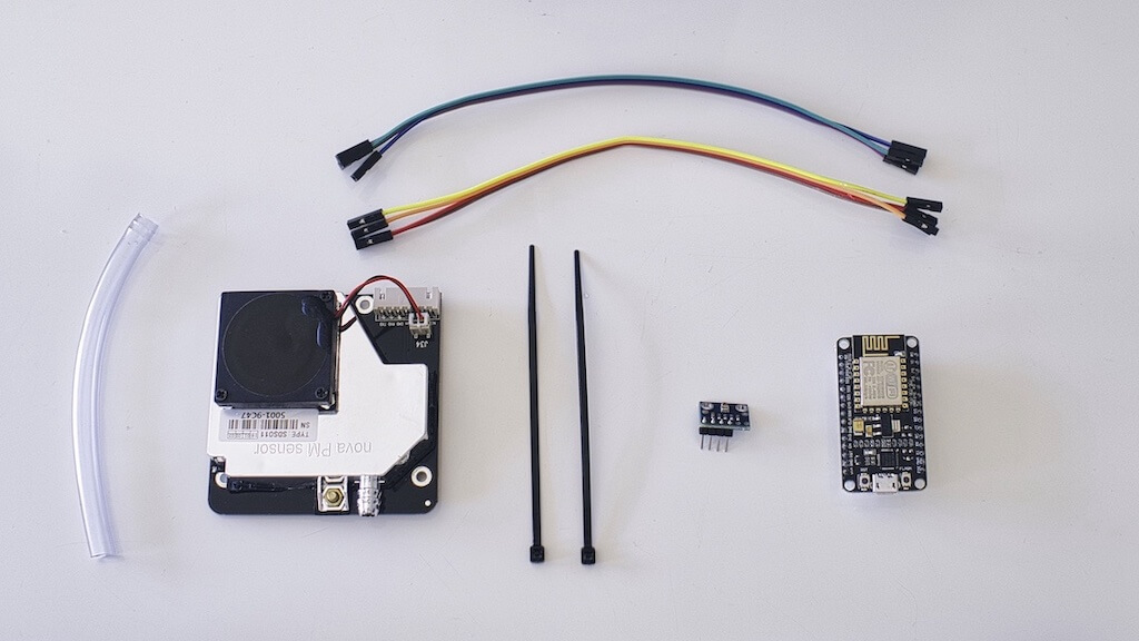
Shopping list
Sensor kit
- Pre-flashed Sensor Kit
Single components
- NodeMCU ESP8266 CPU/WLAN
- SDS011 Fine dust sensor
- BME280 6-PIN, temperature & humidity & air pressure
- via Aliexpress
- via Nettgio
- via Berrybase
- Cable
- USB cable e.g.: flat 2m Micro-USB
- Power supply USB
- Cable straps
- Flexible tube, if possible not transparent, diameter 6 mm, length approx. 20cm DIY store
- Weather protection, Marley Silent HT Arc DN 75 87°
🙌 Great, you decided to buy the parts online! Unfortunately the delivery can take from days up to three weeks. Until then enjoy your life️.
Driver & firmware
We already prepared the firmware. You only have to install drivers and flash your NodeMCU (ESP8266).
To communicate with your NodeMCU (ESP8266) you need usb2serial drivers for your operating system.
The chipset for NocdeMCUs v3 is usually CH341, just check the back of your NodeMCU (ESP8266) to find some technical information.
Choose the link that corresponds to the operating system of your computer.
Windows
Drivers for NodeMCU (ESP8266) V2 (CP2102) for Windows
- Windows 10 — Windows 10 should be able to automatically download these
- Windows 7/8/8.1 — 32-bit version — not supporting 64-bit version OS
Driver for NodeMCU (ESP8266) V3 (CH340/CH341) for Windows
- Windows — Windows 10 should be able to automatically download these
Extract the downloaded file for Windows
- for NodeMCU (ESP8266) V2: Open the folder CP210x and double click on the application CP210xVCPInstaller_x64 (or x86)
- for NodeMCU (ESP8266) V3: open the folder CH341SER and double click on the application SETUP.
MacOS
MacOS Drivers
- NodeMCU V2
- NodeMCU V3
Extract the downloaded file for MacOS
- for V2: Unzip the folder CP210x and double click on the application CP210xVCPInstaller_x64 (or x86)
- for V3: Unzip the folder CH341SER and double click on the application SETUP.
- in case «No boards found»: restart your Mac
Linux
No drivers need to be installed. Chip should be supported directly (verifiable with dmesg)
Firmware Flasher
Support for multiple Operating Systems: Windows, MacOS and Linux.
- airRohr Flashing Tool
- Source Code
Connect NodeMCU to your computer with a short micro-USB cable (choose one shorter than 1 Meter, otherwise the installation may fail). Select latest_en.bin (or another language version) and click “Upload”. Wait until the process is done. Now we can assemble the sensor.
Linux: Set permissions as executable
After the download you may have to set the permission to executable. This can be done with the command: chmod o+x <download filename>
If you see the error message «unable to connect to port /ttyUSB0», you need to add yourself to the dialout group: sudo usermod -a -G dialout $USER then logout and login again.
A big thanks goes to Piotr, from Poland, for his help! 🙋♂️
MacOS: how to run a unverified app
Right click and open the application several times and always confirm with «Open».
Here is a short video on Youtube 👉 https://youtu.be/1KZiP94TYjw
Assemble
⚠️ IMPORTANT NOTE Before assembling install the firmware! See firmware flasher section.
NodeMCU v3
Note: Our instructions refer to version 3 of the NodeMCU. This can be recognized by the connections VU and G (see drawing).
Copyright: roman-minyaylov, MIT License
When you are done, this is how it should look like
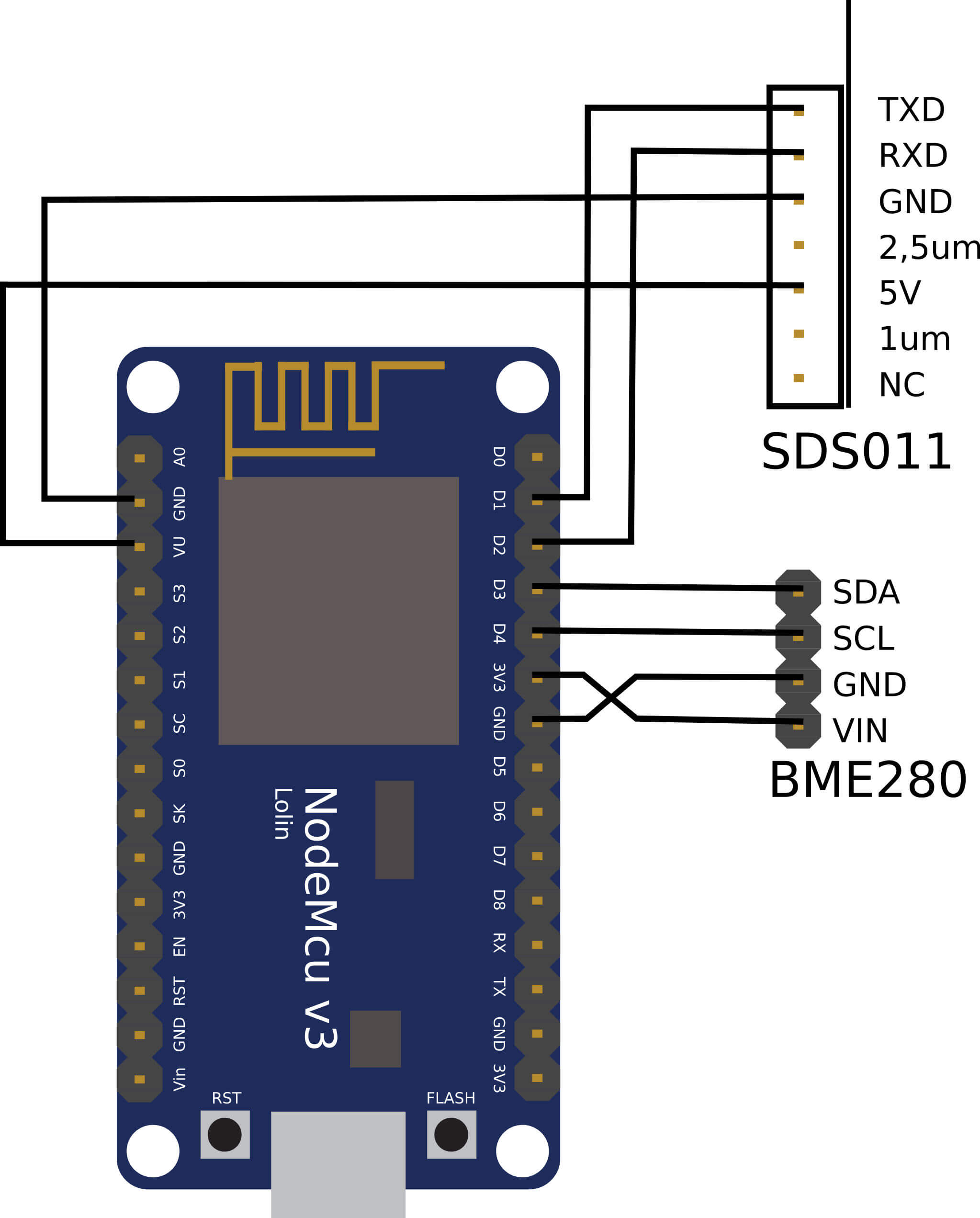
Wire the SDS011
Pins are numbered from RIGHT to LEFT, make sure when connecting the cables are sitting on the pins, as most Dupont cables also fit inbetween the pins.
SDS011 Pin 1 -> Pin D1 / GPIO5
SDS011 Pin 2 -> Pin D2 / GPIO4
SDS011 Pin 3 -> GND
SDS011 Pin 4 -> unused
SDS011 Pin 5 -> VU (NodeMCU v3) / VIN (NodeMCU v1,v2)
SDS011 Pin 6 -> unused
SDS011 Pin 7 -> unused
💡 You can find a list of sensors supported by our firmware
Solder together BME280

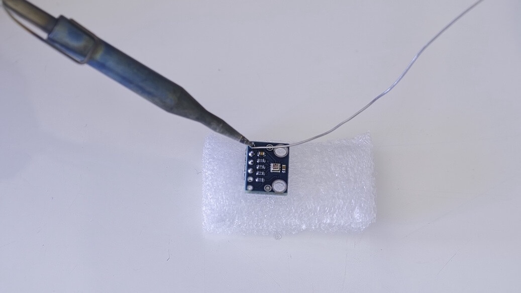
Connect the pin header with the BME280 board. Solder it from the backside. The gaps between the pins are very small so be patient and careful.
The trick is to put the soldering iron tip to the pin, warm it up a little, and then lightly apply the solder.
Wire the BME280
Pins are numbered from LEFT to RIGHT.
VIN -> Pin 3V3 (3.3V)
GND->  GND/G
SDA -> PIN D3
SCL -> Pin D4
Tie everything together
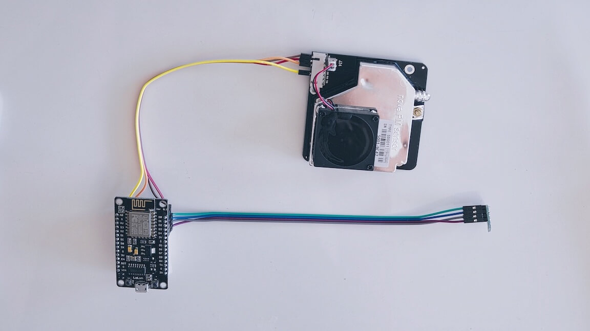
Tie NodeMCU and SDS011 together

Use a cable tie to link the NodeMCU (ESP8266) and the SDS011 sensor so that the Wifi antenna points away from the sensor
Connect flexible tube
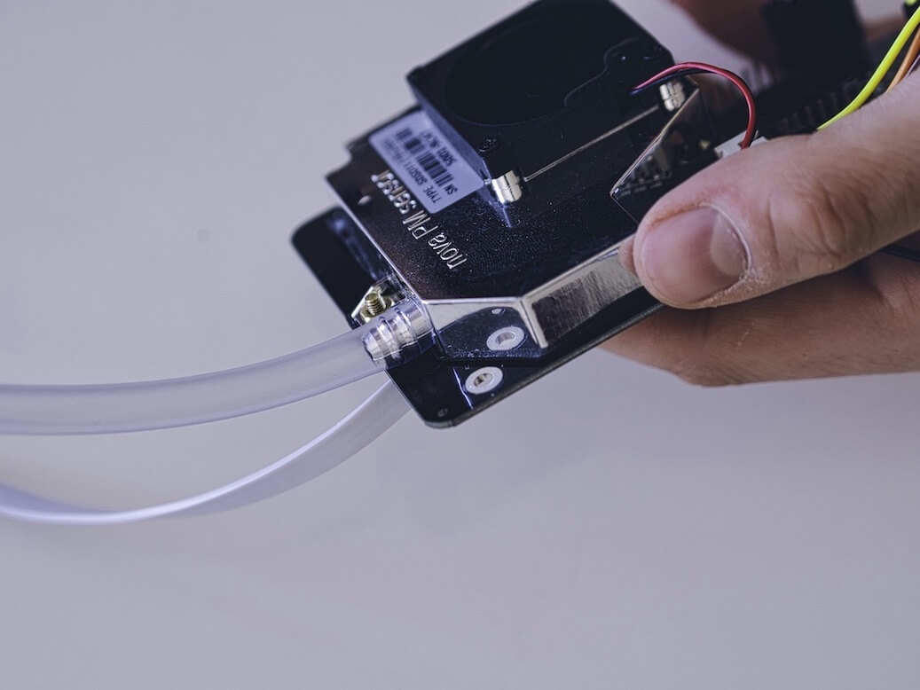

- connect the flexible tube to the SDS011 sensor
- Use another cable tie to attach the BME280 temperature sensor to the tube
- Pass the USB cable through the tube. Mount the SDS011 with the NodeMCU facing to the top and the fan facing to the bottom
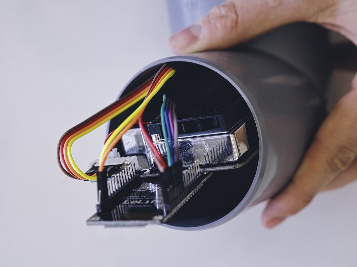
Push in sensor into the pipe
- Push the parts into the tube, so it’s jammed inside
- USB cable, flexible tube and BME280 should look out of the tube’s end
- Push the other pipe onto the first one.
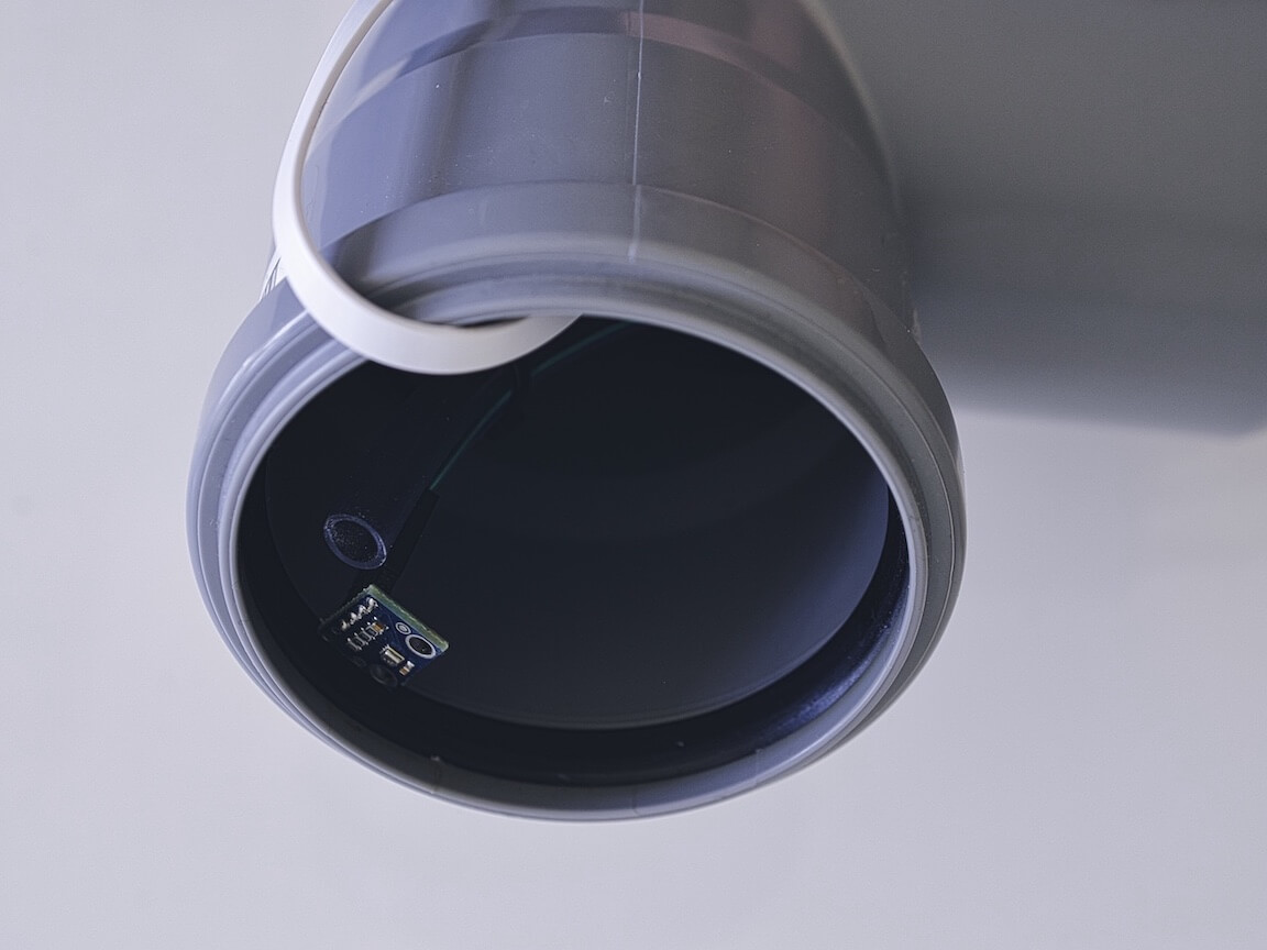
Finishing
- Position the temperature sensor on the flexible tube, so that it’s on the edge of the pipe.
- Cut off the flexible tube at the end of the pipe
- Optional: you can cover the open ends of the tube with a fine mesh. So air can circulate but insects stay outside
Placement
Ideal place would be 1.5 to 3.5 meters above the street and well ventilated. However, this cannot be done for all people because, therefore, information such as the height above the ground and the position to the street is requested during registration.
Configure
Get the unique station ID
-
Connect the station to a USB cable to power up the sensor.
-
The station will attempt to connect to the configured WiFi network. For a new set up, the connection will fail and the station will create a WiFi network with the name
Particulate Matter ID,Feinstaubsensor-IDorairRohr-ID. The ID is the ChipID (for example 13597771). Please note this number down, as you will need it for the registration -
Connect to the WiFi network created by the station on your computer or smartphone. The default password for this network is ‘airrohrcfg’. Wait until the connection is established.
Android: If the connection disconnects immediately, you may have to deactivate the option ‘Smart network switch’ under ‘Connections -> WiFi -> Advanced’. -
Open your browser and type in http://192.168.4.1/.
⚠️ Please note It may take a few tries for the NodeMCU to connect to the home WiFi network. Please be patient and try the steps several times until it works. If the configuration of the sensor has worked, the station WiFi network will not available and the configuration page will no longer accessible under this IP 192.168.4.1
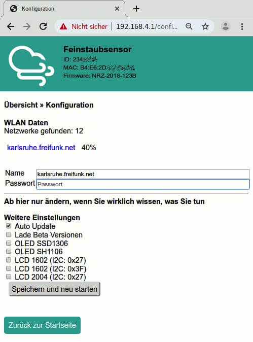
Configure the station
-
In the ‘Configuration’ page enter your SSID (name of your home WiFi network), the network security key (under Windows) or WiFi password.
-
If you are using the recommended fine dust sensor (SDS011), no further configuration changes are necessary.
-
Click ‘Save configuration and restart’ button. The station will restart and will no longer be accessible in this way when it connects to your home WiFi network.
Verify the station is correctly configured
If you made no other changes in the previous step other than WiFi network configuration, the sensor will now start recording and uploading the data. You can verify that everyting is working correctly after about 10 minutes by navigating to the following pages. On these pages search for the ChipID (in the example above the 13597771).
- Sensor data
- WiFi signal data
Register
Create an account
Go to devices.sensor.community to create an account and become a part of the open data network.
Register your device
Once you create an account and log in, you will be able to register your device. Fill out the form to register your device. Navigate to Home -> (Login) — Sensors -> Register new sensor
- sensor ID is the ChipID of the ESP8266 (NodeMCU) that you noted down before
- your email address (will not be published)
- your address: Street with house number, postcode and city. Click on «Lookup entered address» to get the location coordinates (will be rounded off). Check the position of the pin, change it if needed
- set a personal sensor name to make it easier to separate them if you have multiple sensors (like garden, sensor for mom,…)
- the surroundings of the station — e.g. height above ground, side of the road, high traffic volume, free field or similar
Troubleshoot
Transmitting problems?
Enter the following in the browser with your own data: https://api-rrd.madavi.de/grafana/d/GUaL5aZMz/pm-sensors?orgId=1&var-chipID=esp8266-[ID]
The [ID] can also be searched for in input field in the upper left corner https://api-rrd.madavi.de/grafana/d/GUaL5aZMz/pm-sensors?orgId=1
- Is the sensor registered via https://devices.sensor.community/ and is the sensor visible on the map?
- Was the WLAN signal level weak in the past? here is the signal log server-side:
https://api-rrd.madavi.de/grafana/d/Fk6mw1WGz/wifi-signal?orgId=1&var-chipID=esp8266-[ID]
- Was the WLAN signal level weak in the past? here is the signal log server-side:
USB cable problems?
- Check power supply: USB cable
- Reboot (disconnect power supply, e.g. pull USB plug)
- Is the WLAN Config OK (the sensor connects to the configured WLAN) If not:
- does the sensor open an AP (in the first 2-7 minutes after a reboot)?
- Look for
airrohr-[ID]WLAN network. Patience, it may take 1-2 minutes after boot.
- Check on your own router if the sensor is logged into the network, then remember the IP
- alternatively use «Discovery» in the flashtool
- If yes: connect to the sensor via IP with a browser
http://[ip-of-the-sensor]/, the interface should appear - If no: the ESP has problems, e.g. power supply insufficient, reboot loop or similar
- Connect USB to a computer and view the log
-
Track text on serial interface with serial terminal program (Settings: baud 9600, 8N1)
- Linux: screen, minicom, cutecom; Windows: Tera Term; MacOS: screen, minicom, …
- possibly suitable usb2serial drivers are still necessary, see https://github.com/opendata-stuttgart/meta/wiki/Firmware-einspielen
-
There you should be able to see what the sensor is doing (boot messages, WLAN connection or AP, measurement — only after 3 minutes)
-
Electronics problems?
- Remove sensor electronics from the housing and observe
- Check/replace power supply again
- does ESP flash shortly after reboot?
- SDS011: red LED/fan on after reboot?
- check/replace the cables to the sensors again
Provide feedback
Saved searches
Use saved searches to filter your results more quickly
Sign up
Search for your product name or keyword
NodeMCU is an open-source firmware that helps you to prototype your IOT product with code like Arduino, but interactively in a Lua script.
This NodeMCU Development Kit is based on the ESP8266 and integrates GPIO, PWM, IIC, 1-Wire and ADC all in one board.
Features:
- LoLin V3 version
- CH340G USB Interface
- Wireless 802.11 b / g / n standard
- Support STA / AP / STA + AP three operating modes
- Built-in TCP / IP protocol stack to support multiple TCP Client connections (5 MAX)
- D0 ~ D8, SD1 ~ SD3: used as GPIO, PWM, IIC, etc., port driver capability 15mA
- AD0: 1 channel ADC
- Power input: 4.5V ~ 9V (10V MAX), USB-powered
- Continuous Current: ≈70mA (200mA MAX), Standby: <200uA
- Transfer rate: 110-460,800bps
- Support UART / GPIO data communication interface
- Remote firmware upgrade (OTA)
- Support Smart Link Smart Networking
- Working temperature: -40 ℃ ~ + 125 ℃
Reference:
Arduino Software (IDE) download link: http://envistia.info/arduinoide
NodeMCU Firmware & Development Kit Website: http://envistia.info/nodemcu
ESP8266 Community Forum: http://envistia.info/esp8266-forum
How to program the ESP8266 using Arduino IDE tutorial videos and websites:
http://envistia.info/youtube-nodemcu-blink
https://envistia.info/electromania-how-to-program-esp8266 (Electromania website)
http://envistia.info/youtube-nodemcu-gettingstarted
https://envistia.info/youtube-nodemcu-gettingstarted2
The CH340G USB drivers may need to be installed on your computer before using this NODEMCU board with the Arduino IDE. If the Arduino IDE cannot communicate with your board, it is probably because the CH340G driver is not installed on your computer.
To install the CH340G driver on your computer:
The CH340 USB IC is made by WCH. You can find the latest version of their drivers in their English translated website here:
http://www.wch-ic.com/downloads/CH341SER_ZIP.html
Click on the “download” button on the WCH page to download the ch341ser.zip file to your computer.
Unzip (extract) the ch341ser.zip file.
Run the Setup application in the CH341SER folder of the unzipped file. See the screenshot below:
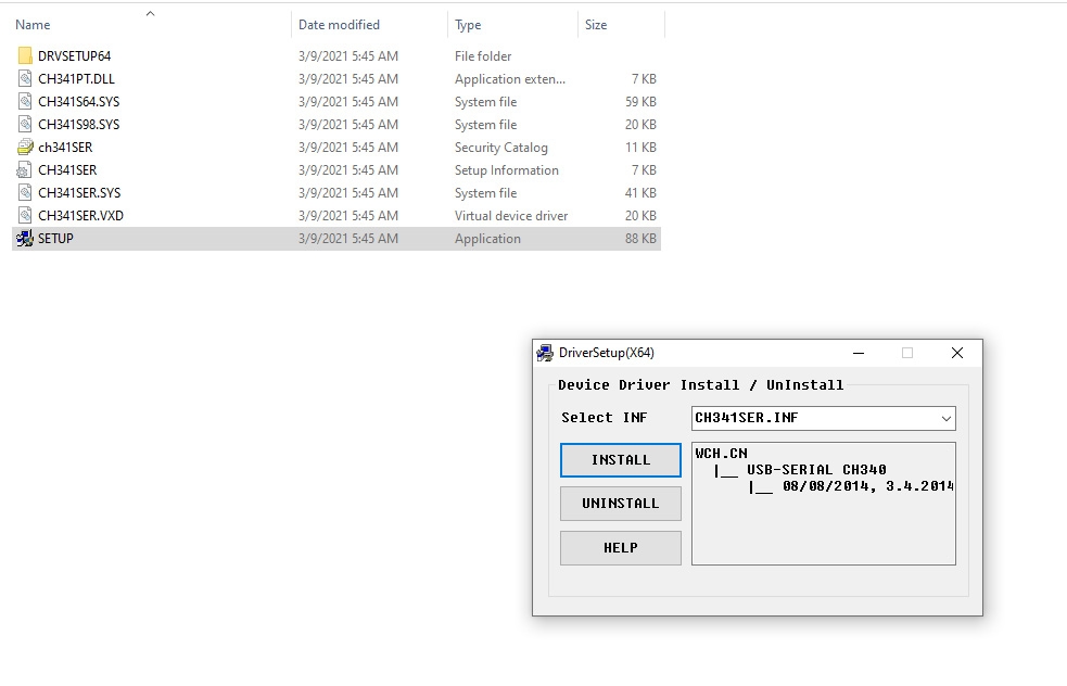
Click the “Uninstall” button first to remove any old versions, then click on the “Install” button.
CH340G Driver Verification for Windows:
To verify that your CH340G driver is working, you should see a difference in the Windows Device Manager and Arduino IDE Ports after plugging the NODEMCU board with a CH340 into a USB port on your computer.
Device Manager
To check that the CH340 associates to a COM port, open the Windows Device Manager. You can click the Start or ⊞ (Windows) button and type “device manager” to search for the application.
After opening the Device Manager, you will need to open the Ports (COM & LPT) tree. The CH340 should show up as USB-SERIAL CH340 (COM##). Depending on your computer, the COM port may show up as a different number.

Arduino IDE
If you have the Arduino IDE installed, you should also see a change in the number of available COM Ports (you may need to restart the Arduino IDE for the board to populate). Without the CH340 connected to your computer, in the IDE click on Tools > Port. Take note of the Serial Ports available:
Connect the NODEMCU board with the CH340 to your computer’s USB port. Click somewhere else on the screen for the menu to refresh itself. Then go back to Tools > Port. A new COM port should appear. By process of elimination, the CH340 should have associated to the new COM port. Select this COM port in order to connect the IDE to your Arduino board.
In the example shown in these two screen shots, the new NODEMCU CH340 board is associated to COM Port 3.
NodeMCU ESP8266 Pinout:

Copyright © 2016-2021 Envistia Mall
http://www.envistiamall.com
EM-MICRP-0007