
dtc
Device Tree Compiler for Windows
The Device Tree Compiler (DTC) is the toolchain for building device tree
source files (.dts) into the binary format (.dtb).
libfdt is a BSD-licenses library for manipulating device tree files. Since
it is BSD licensed, it may be freely incorporated into other software such
as firmware and operating system loaders.
Home Page
http://devicetree.org/Device_Tree_Compiler
Windows Port
This is a Windows port of original Device Tree Compiler which can be built
with MinGW toolchains downloaded from http://mingw.org.
kandi X-RAY | dtc Summary
kandi X-RAY | dtc Summary
dtc is a C library. dtc has no bugs, it has no vulnerabilities and it has low support. You can download it from GitHub.
Device Tree Compiler for Windows. The Device Tree Compiler (DTC) is the toolchain for building device tree source files (.dts) into the binary format (.dtb). libfdt is a BSD-licenses library for manipulating device tree files. Since it is BSD licensed, it may be freely incorporated into other software such as firmware and operating system loaders.
Support
dtc has a low active ecosystem.
It has 8 star(s) with 2 fork(s). There are 3 watchers for this library.
It had no major release in the last 6 months.
dtc has no issues reported. There are no pull requests.
It has a neutral sentiment in the developer community.
The latest version of dtc is current.
Quality
dtc has 0 bugs and 0 code smells.
Security
dtc has no vulnerabilities reported, and its dependent libraries have no vulnerabilities reported.
dtc code analysis shows 0 unresolved vulnerabilities.
There are 0 security hotspots that need review.
License
dtc does not have a standard license declared.
Check the repository for any license declaration and review the terms closely.
Without a license, all rights are reserved, and you cannot use the library in your applications.
Reuse
dtc releases are not available. You will need to build from source code and install.
It has 1 lines of code, 0 functions and 1 files.
It has low code complexity. Code complexity directly impacts maintainability of the code.
Top functions reviewed by kandi — BETA
kandi’s functional review helps you automatically verify the functionalities of the libraries and avoid rework.
Currently covering the most popular Java, JavaScript and Python libraries. See a
Sample of dtc
Get all kandi verified functions for this library.
dtc Key Features
No Key Features are available at this moment for
dtc
.
dtc Examples and Code Snippets
No Code Snippets are available at this moment for
dtc
.
Vulnerabilities
No vulnerabilities reported
Install dtc
You can download it from GitHub.
Support
For any new features, suggestions and bugs create an issue on GitHub.
If you have any questions check and ask questions on community page Stack Overflow .
Find more information at:
Find, review, and download reusable Libraries, Code Snippets, Cloud APIs from over 650 million Knowledge Items
Find more libraries

Join our monthly Unpacking Software livestream to hear about the latest news, chat and opinion on packaging, software deployment and lifecycle management!
Learn More

Join the Chocolatey Team on our regular monthly stream where we put a spotlight on the most recent Chocolatey product releases. You’ll have a chance to have your questions answered in a live Ask Me Anything format.
Learn More
Join us for the Chocolatey Coding Livestream, where members of our team dive into the heart of open source development by coding live on various Chocolatey projects. Tune in to witness real-time coding, ask questions, and gain insights into the world of package management. Don’t miss this opportunity to engage with our team and contribute to the future of Chocolatey!
Learn More

Webinar from
Wednesday, 17 January 2024
We are delighted to announce the release of Chocolatey Central Management v0.12.0, featuring seamless Deployment Plan creation, time-saving duplications, insightful Group Details, an upgraded Dashboard, bug fixes, user interface polishing, and refined documentation. As an added bonus we’ll have members of our Solutions Engineering team on-hand to dive into some interesting ways you can leverage the new features available!
Watch On-Demand

Join the Chocolatey Team as we discuss all things Community, what we do, how you can get involved and answer your Chocolatey questions.
Watch The Replays

Webinar Replay from
Wednesday, 30 March 2022
At Chocolatey Software we strive for simple, and teaching others. Let us teach you just how simple it could be to keep your 3rd party applications updated across your devices, all with Intune!
Watch On-Demand

Livestream from
Thursday, 9 June 2022
Join James and Josh to show you how you can get the Chocolatey For Business recommended infrastructure and workflow, created, in Azure, in around 20 minutes.
Watch On-Demand

Livestream from
Thursday, 04 August 2022
Join Paul and Gary to hear more about the plans for the Chocolatey CLI in the not so distant future. We’ll talk about some cool new features, long term asks from Customers and Community and how you can get involved!
Watch On-Demand

Livestreams from
October 2022
For Hacktoberfest, Chocolatey ran a livestream every Tuesday! Re-watch Cory, James, Gary, and Rain as they share knowledge on how to contribute to open-source projects such as Chocolatey CLI.
Watch On-Demand
This page covers the generation of devicetree source (DTS) files using Xilinx tools as well as the building/compiling of these source files using standard open-source tools. In particular, use of the Xilinx Devicetree Generator (DTG) will be covered for generating DTS files from a Xilinx hardware project while the devicetree compiler (DTC) will be covered for compiling DTS files into a devicetree binary (DTB). Although the primary use of the DTB is to provide it to the Linux kernel so that Linux can be initialized to specific hardware correctly, the DTB can also be used with QEMU to emulate hardware for both Linux and standalone systems.
Table of Contents
Child Pages
Devicetree 101
What is devicetree?
Device tree or simply called DT is a data structure that describes the hardware. This describes the hardware which is readable by an operating system like Linux so that it doesn’t need to hard code details of the machine.
Linux uses the DT basically for platform identification, run-time configuration like bootargs and the device node population.
Devicetree Basics
Each driver or a module in the device tree is defined by the node and all its properties are defined under that node. Based on the driver it can have child nodes or parent node.
For example a device connected by SPI bus will have SPI bus controller as its parent node and that device will be one of the child node of spi node. Root node is the parent for all the nodes.
Under the root node typically consists of
1) CPUs node information
2) Memory information
3) Chosen can have configuration data like the kernel parameters string and the location of an initrd image
4) Aliases
5) Nodes which define the buses information
Devicetree Syntax Example
/ {
    compatible = "xlnx,zynqmp";
    #address-cells = <2>;
    #size-cells = <2>;

    cpus {
       #address-cells = <1>;
       #size-cells = <0>;

       cpu0: cpu@0 {
                compatible = "arm,cortexa53", "arm,armv8";
                device-type = "cpu";
                enable-method = "psci";
                operating-points-v2 = <&cpu_opp_table>;
                reg = <0x0>;
                cpu-idle-states = <&CPU_SLEEP_0>;
        };

        cpu1: cpu@1 {
               compatible = "arm,cortexa53", "arm,armv8";
               device-type = "cpu";
               enable-method = "psci";
               operating-points-v2 = <&cpu_opp_table>;
               reg = <0x1>;
               cpu-idle-states = <&CPU_SLEEP_0>;
        };
  };

  chosen {
           bootargs = "earlycon clk_ignore_unused";
  };

  memory {
          device-type = "memory";
          reg = <0x0 0x0 0x0 0x80000000>, <0x00000008 0x0 0x0 0x80000000>;
  };

  amba_apu: amba_apu@0 {
              compatible = "simple-bus";
              #address-cells = <2>;
              #size-cells = <1>;
              ranges = <0 0 0 0 0xffffffff>;
              gic: interrupt-controller@f9010000 {
                        compatible = "arm,gic-400", "arm,cortex-a15-gic";
                        #interrupt-cells = <3>;
                        reg = <0x0 0xf9010000 0x10000>,
                               0x0 0xf9020000 0x20000>,
                               0x0 0xf9040000 0x20000>,
                               0x0 0xf9060000 0x20000>,
                        interrupt-controller;
                        interrupt-parent = <&gic>;
                        interrupts =<1 9 0xf04>;
              };
  };

  amba: amba {
          compatible = "simple-bus";
          #address-cells = <2>;
          #size-cells = <2>;
          ranges;
          can0: can@ff060000 {
                     compatible = "xlnx,zynq-can-1.0";
                     clock-names = "can_clk", "pclk";
                     reg =<0x0 0xff060000 0x0 0x1000>;
                     interrupts = <0 23 4>;
                     interrupt-parent = <&gic>;
                     tx-fifo-depth = <0x40>;
                     rx-fifo-depth = <0x40>;
                     power-domains = <&pd_can0>;
          };
  };
Devicetree Properties
compatible: The top-level compatible property typically defines a compatible string for the board, and then for the SoC.
Values always given with the most-specific first, to least-specific last.
#address-cells: Property indicate how many cells (i.e 32 bits values) are needed to form the base address part in the reg property.
#size-cells: The size part of the reg property.
interrupt-controller: Is a boolean property that indicates that the current node is an interrupt controller.
#interrupt-cells: Indicates the number of cells in the interrupts property for the interrupts managed by the selected interrupt controller.
interrupt-parent: Is a phandle that points to the interrupt controller for the current node. There is generally a top-level interrupt-parent definition for the main interrupt controller.
Devicetree (DTG)
The DTG is intended to help users build their hardware-specific DTS file. Building a DTS for custom hardware will always be a somewhat manual process but the DTG can help jump-start users to a fairly advanced starting point. This is because a lot of information captured in a DTS can be extracted from information in the hardware hand-off file (XSA). DTG will populate various DTS files with as much information as it can based on a supplied XSA file and then the user will be expected to fill-in the blanks or adjust as needed.
Version Check
The procedure for using the DTG varies for older versions of Xilinx tools. Additionally, for some tool versions, there may be GUI flows versus CLI flows. The «Generate DTS Files» section below provides several sub-sections for each of these different procedures. If you’re not using the latest version of Xilinx tools make sure you refer to the appropriate sub-section beyond the first one presented.
Task Dependencies (Pre-requisites)
-
DTG Source
-
XSA Hardware hand-off file generated by Xilinx Vivado tool (previously HDF)
- Xilinx Vitis installation (or previously Xilinx SDK)
Task Output Products
The DTG generates DTS files with *.dts and *.dtsi file extensions. There will be a single top-level *.dts file with «include» statements to reference separate DTS include (DTSI) files. Using DTSI files allows information to be organized amongst different files. For example, as described in more detail below, one DTSI can be used to describe fixed hardware (i.e. fixed in silicon) while another DTSI can be used to describe dynamic hardware (i.e. IP in the programmable logic).
Generally for the SOCs there will be a static dts/dtsi files, but when it comes to the FPGA there can be many complicated designs which the peripheral logic(PL) IPs may vary or might be having different configurations.
For these complicated FPGA designs we require a Device tree generator(DTG) where it can generate the dts/dtsi automatically for those designs.
Once we generate there will be different files available in the output directory, say for example pl.dtsi, pcw.dtsi, system-top.dts, zynqmp.dtsi, zynqmp-clk-ccf.dtsi, pl-partial-*.dtsi(the suffix of rprm will be added and this files will get generated only for partial/dfx xsa files). These files are described below.
- pl.dtsi: This is a file where all the memory mapped peripheral logic(PL) IP nodes will be available.
- pcw.dtsi: This is a file where the dynamic properties where the PS peripheral needs.
- system-top.dts: This is a file where it contains the memory information, early console and the boot arguments.
- zynqmp.dtsi: This file contains all the PS peripheral information and also the cpu info.
- zynqmp-clk-ccf.dtsi: This file contains all the clock information for the peripheral IPs.
- pl-partial-<RPRM>.dtsi: This is a file where all the memory mapped IP nodes for dynamic function exchange designs(DFX).
- pl-partial-custom-<RPRM>.dtsi: This is a file where we can customize the dfx ip nodes. This will get generated when CONFIG.partial_overlay_custom_dts is set
- If user issues %xsct set_property CONFIG.partial_overlay_custom_dts «pl-partial-final.dts» command then pl-partial-<RPRM>.dtsi and pl-partial-custom-<RPRM>.dtsi will get created and included in pl-partial-final<RPRM>.dts
- user should do his changes in pl-partial-custom-<RPRM>.dtsi. With this user can create pl-partial-<rprm>.dtbo or pl-partial-final<RPRM>.dtbo based on his requirements.
- pl-custom.dtsi: This will get generated only when CONFIG.overlay_custom_dts is set. This flag is useful when user want to customize pl.dtsi nodes with user changes when using overlays.
- If user issues %xsct set_property CONFIG.overlay_custom_dts «pl-final.dts» command then pl.dtsi and pl-custom.dtsi will get created and included in pl-final.dts
- user should do his changes in pl-custom.dtsi. With this user can create pl.dtbo or pl-final.dtbo based on his requirements.
Apart from these files, based on the board it will generate one more board.dtsi file under the same output directory dt/. For example, if board is zcu111-reva then it generates dt/zcu111-reva.dtsi.
- zcu111-reva.dtsi: It contains all the board specific properties like i2c might be connected to some slave etc.
The actual files output will vary based on the device architecture (e.g. ZynqUS+ vs Zynq-7000 vs MicroBlaze).
Step 1: Fetch DTG Source
DTG is an open source utility with the source code published on the Xilinx GitHub site. It uses an interpreted language (Tcl) so there’s no need to compile the source.
git clone https://github.com/Xilinx/device-tree-xlnx
cd device-tree-xlnx
git checkout <xilinx_rel_v20XX.X>
In the last command above <xilinx-v20XX.X> should be replaced with a valid tag value (for example «xilinx_rel_v2023.1»). Available tags can be listed using the command «git tag».
Step 2: Generate DTS Files
Only follow the individual sub-section below that applies to your use-case.
Generate DTS Files Using XSCT
- Source Xilinx design tools
-
Run XSCT (available as of 2015.1 tool release)
-
Open XSA/HDF file
hsi open_hw_design <design_name>.<xsa|hdf>
-
Set repository path (clone done in previous step in SDK) (On Windows use this format set_repo_path {C:\device-tree-xlnx})
hsi set_repo_path <path to device-tree-xlnx repository>
-
Create SW design and setup CPU. The -proc option is typically one of these values: for Versal «psv_cortexa72_0«, for ZynqMP «psu_cortexa53_0«, for Zynq-7000 «ps7_cortexa9_0«, for Microblaze «microblaze_0«. However, users should extract the processor cell name this as shown below. This will return a list of valid processors that users should use.
set procs [hsi get_cells -hier -filter {IP_TYPE==PROCESSOR}]
puts "List of processors found in XSA is $procs"
hsi create_sw_design device-tree -os device_tree -proc psv_cortexa72_0
-
Generate DTS/DTSI files to folder my_dts where output DTS/DTSI files will be generated
hsi generate_target -dir my_dts
-
Clean up.
hsi close_hw_design [hsi current_hw_design]
exit
Note that to compliment XSCT User Guide documentation some tips on using HSI can be found here: HSI debugging and optimization techniques. For example, a command that lists all processor cells in the hardware design can be found there (i.e. IP_TYPE==PROCESSOR); these processor cell names represent valid values for the -proc option in step 5 above.
Generate DTS Files Using Xilinx SDK (GUI flow: tool version 2014.2-2019.1)
Generate HDF file from hardware project (if not already available)
- Open the hardware project in Vivado.
- Generate Block Design
IP Integrator: Generate Block Design
# Export the hardware system to SDK:
Vivado Menu: File > Export > Export Hardware
(In <project_name>.sdk HDF file is generated)
Generate a Device Tree Source (.dts/.dtsi) files from SDK
-
Open SDK from Vivado or open SDK via command line (xsdk -hwspec <filename>.hdf -workspace <workspace>
Vivado Menu: File > Launch SDK
-
The Device Tree Generator Git repository needs to be cloned from the Xilinx. See the Fetch Sources page for more information on Git.
# Otherwise for SDK 2014.2 use this repo:
git clone git://github.com/Xilinx/device-tree-xlnx.git
-
Add the BSP repository in SDK (for SDK 2014.2 and later select «device-tree-xlnx» from the checked out git area):
SDK Menu: Xilinx Tools > Repositories > New... (<bsp repo>) > OK
-
Create a Device Tree Board Support Package (BSP):
SDK Menu: File > New > Board Support Package > Board Support Package OS: device-tree > Finish
- A BSP settings window will appear. This window can also be accessed by opening the Device Tree BSP’s system.mss file and clicking ‘Modify this BSP’s Settings’. Fill in the values as appropriate:
- The ‘bootargs’ parameter specifies the arguments passed to the kernel at boot time (kernel command line). ***
- The ‘console device’ parameter specifies which serial output device will be used. Select a value from the drop-down.
The .dts/.dtsi files are now located in <SDK workspace>/device_tree_bsp_0/ folder.
*** e.g. console=<tty>,<baudrate> root=/dev/ram rw ip=:::::eth0:dhcp earlyprintk
*** Some example values for <tty> are ttyPS0 when using Zynq, ttyUL0 when using the UART Lite soft ip, or ttyS0 when using the UART16550 soft ip.
Generate DTS Files Using HSI (CLI flow deprecated by XSCT)
As of the 2019.2 release of tools HSI is no longer available as a standalone utility and HSI commands must be run from XSCT. Also note that XSCT has supported HSI commands since its introduction in the 2015.1 tool release.
- Source Xilinx design tools
-
Run HSI (tool releases 2014.4 — 2019.1)
-
Open HDF file
open_hw_design <design_name>.hdf
-
Set repository path (clone done in previous step in SDK) (On Windows use this format set_repo_path {C:\device-tree-xlnx})
set_repo_path <path to device-tree-xlnx repository>
-
Create SW design and setup CPU (for ZynqMP psu_cortexa53_0, for Zynq ps7_cortexa9_0, for Microblaze microblaze_0)
create_sw_design device-tree -os device_tree -proc ps7_cortexa9_0
-
set_property CONFIG.periph_type_overrides «{BOARD zcu102-rev1.0}» [get_os]
set_property CONFIG.periph_type_overrides "{BOARD zcu102-rev1.0}" [get_os]
-
Generate DTS/DTSI files to folder my_dts where output DTS/DTSI files will be generated
generate_target -dir my_dts
- In the generated my_dts folder zcu102-rev1.0.dtsi file should be present.
Generate DTS Files Using HSM (CLI flow deprecated by XSCT)
As of the 2019.2 release of tools HSM is no longer available as a standalone utility and has been deprecated by HSI commands within XSCT. Also note that XSCT has supported HSI commands since its introduction in the 2015.1 tool release.
- Source Xilinx design tools
-
Run HSM (tool releases 2014.4 — 2019.1)
-
Open HDF file
open_hw_design <design_name>.hdf
-
Set repository path (clone done in previous step in SDK) (On Windows use this format set_repo_path {C:\device-tree-xlnx})
set_repo_path <path to device-tree-xlnx repository>
-
Create SW design and setup CPU (for ZynqMP psu_cortexa53_0, for Zynq ps7_cortexa9_0, for Microblaze microblaze_0)
create_sw_design device-tree -os device_tree -proc ps7_cortexa9_0
-
Generate DTS/DTSI files to folder my_dts where output DTS/DTSI files will be generated
generate_target -dir my_dts
Generate DTS Files Using XPS/SDK (legacy GUI flow: tool versions 2014.1 and prior)
- Open the hardware project in XPS.
-
Export the hardware system to SDK.
NOTE: The GitHub repository cloned in the following instructions is no longer available online. You can download archived source from AR# 75492
-
XPS Menu: Project > Export Hardware Design to SDK... > Export && Launch SDK
# The Device Tree Generator Git repository needs to be cloned from the Xilinx. See the [[www/Fetch Sources|Fetch Sources]] page for more information on Git. Note that there are two repos for differing SDK versions below.
> [[code]]
> > > > > > > > > > > > > > > > > > > > > > > > > > > > > > > > > > > > > > > > > > > > > > > > > > > > > > > > > > git clone git://github.com/Xilinx/device-tree.git bsp/device-tree_v0_00_x//
> > > > > > > > > > > > > > > > > > > > > > > > > > > > > > > > > > > > > > > > > > > > > > > > > > > > > > > > //[[code]]//
> > > > > > > > > > > > > > > > > > > > > > > > > > > > > > > > > > > > > > > > > > > > > > > > > > > > > > > > # //Note: In order for SDK to be able to import the Device Tree Generator correctly, the file and directory hierarchy needs to look like://
> > > > > > > > > > > > > > > > > > > > > > > > > > > > > > > > > > > > > > > > > > > > > > > > > > > > > > > > > //<bsp repo>/bsp/device-tree//_v0_00_x/data/device-tree_v2_1_0.mld
> > > > > > > > > > > > > > > > > > > > > > > > > > > > > > > > > > > > > > > > > > > > > > > > > > > > > > > > > //<bsp repo>/bsp/device-tree//_v0_00_x/data/device-tree_v2_1_0.tcl//
> > > > > > > > > > > > > > > > > > > > > > > > > > > > > > > > > > > > > > > > > > > > > > > > > > > > > > > > # Add the BSP repository in SDK (for SDK 2014.2 and later select "device-tree-xlnx" from the checked out git area):
> [[code]]
 > SDK Menu: Xilinx Tools > Repositories > New... (<bsp repo>) > OK
-
Create a Device Tree Board Support Package (BSP):
SDK Menu: File > New > Board Support Package > Board Support Package OS: device-tree > Finish
- A BSP settings window will appear. This window can also be accessed by opening the Device Tree BSP’s system.mss file and clicking ‘Modify this BSP’s Settings’. Fill in the values as appropriate:
- The ‘bootargs’ parameter specifies the arguments passed to the kernel at boot time (kernel command line). ***
- The ‘console device’ parameter specifies which serial output device will be used. Select a value from the drop-down.
The .dts file is now located in <SDK workspace>/<device-tree bsp name>/<processor name>/libsrc/device-tree_v0_00_x/xilinx.dts.
*** e.g. console=<tty>,<baudrate> root=/dev/ram rw ip=:::::eth0:dhcp earlyprintk
*** Some example values for <tty> are ttyPS0 when using Zynq, ttyUL0 when using the UART Lite soft ip, or ttyS0 when using the UART16550 soft ip.
In the Linux source directory, there are also some DTS files available for use in linux-xlnx/arch/<architecture>/boot/dts/.
Step 3: Additional Check for Standalone MicroBlaze Emulation Only
If generating DTS files for emulation of Standalone MicroBlaze applications with QEMU some additional checks should be made and some minimum requirements noted. With regards to requirements, the MicroBlaze sub-system (defined in the Vivado IP Integrator block design) must have at least the following components:
- MicroBlaze Processor
- Memory
- Serial Interface (AXI UART)
- Interrupt Controller (AXI INTC)
Attached is an example DTS with only these minimum requirements:
The generated DTS should be checked, and modified as necessary, to ensure the MicroBlaze node (i.e. / > cpus > microblaze_0) in the pl.dtsi file has the following properties:
- memory
- model
- version
For example:
...
cpus {
		#address-cells = <1>;
		#cpus = <1>;
		#size-cells = <0>;
		microblaze_0: cpu@0 {
			memory = <&lmb_bram>;
			model = "microblaze,8.40.b";
			version = "8.40.b";
...
If a memory node already exists, you may just need to add label to it so it can be referenced («lmb_bram» in above example). The name for the label is arbitrary but most be consistent between the the node definition and reference. For example, if the system has DDR then a label like «ddr_mem» would be more appropriate. If a memory node was not generated (system-top.dts or pl.dtsi) then it must be added manually. An example of adding a memory node to the system-top.dtsi is given below.
...
/ {
	lmb_bram: memory@0 {
               device_type = "memory";
               reg = < 0x0 0x10000000 >;
	} ;
...
DTG Limitations
- zynqmp-clk-ccf.dtsi has static clock node configuration, if user wants to change any of the clock information update those in system-user.dtsi.
- DTG doesn’t support IP that are packaged in a subsystem(multiple BD’s)
- Interrupt port width more than one wont be supported.
- When multicore is enabled for the MAC IPs(if the MAC IPs are more than 1) then there is issue with the label in DTG and it fails. But there wont be an issue if the MAC IP is one and multicore is enabled.
- DTG wont support for generation of private peripheral interrupts(PPI).
- DTG supports the video pipeline generation based on the internal TRD designs as mentioned in the wiki https://xilinx-wiki.atlassian.net/wiki/spaces/A/pages/25329832/Zynq+UltraScale+MPSoC+VCU+TRD+2018.3
- DTG doesn’t support custom IP, For Multimedia use case If there are any custom IPs connected between the video pipeline IPs DTG wont support those, user may need to add the input and output ports.
- For broadcaster IP the output can connect to multiple output ports and DTG cant know which output port is a valid for the correct pipeline.
- If there are multiple similar video pipelines in the design user need to add the input and output port information in the nodes. The below wiki gives some info about how to add the input and output ports.
- DTG limitation for multimedia IPs
- DTG doesn’t support non memory-mapped IP’s.
- With the current DTG implementation not able to populate the ttc timer properties in pcw.dtsi even if the design has ttc ips. In board dtsi file zynq-7000.dtsi/zynqmp.dtsi/versal.dtsi change the ttc timer name to ttctimer then you will see the entries in pcw.dtsi. We will fix this in 2022.2 release.
- when there are multi ethernet ips in the zynqmp design then getting syntax error for the third IP. Closing the clock with «>» resolves the issue in pl.dtsi file
- if the same peripheral connected to both RPU and APU and you want only RPU to access that please disable the status explicitly ‘status = «disabled»‘ as DTG default generates the nodes for all the accessible peripherals.
- If PS ethernet is connected to gmii-to-rgmii Interface User should add ‘phy1’ node references into either board dtsi file or system-user.dtsi files to not see the below build failures. This cannot be autogenerated as DTG doesn’t know the connected board phy info.
ERROR (phandle_references): /axi/ethernet@ff0c0000/mdio/gmii_to_rgmii_1@8: Reference to non-existent node or label «phy1»
ERROR: Input tree has errors, aborting (use -f to force output)
Reference node can be found at https://github.com/Xilinx/device-tree-xlnx/blob/xlnx_rel_v2022.2/device_tree/data/kernel_dtsi/2022.2/BOARD/zcu1275-revb.dtsi#L54-L74
New Features:
- Multi concat block support added
- Added DPU IP support
- Replaced the hardcoded values with the macros for reset and power.
- Added dma channels for axi_mcdma IP support in DTG.
- Generate the memory node for each axi_noc IP for Versal
- Added dfx support in DTG
- generating the aie clock node for versal designs if they have aie ip.
- For aie node you can find the detailed doc in below
- https://github.com/Xilinx/linux-xlnx/blob/master/Documentation/devicetree/bindings/soc/xilinx/xlnx%2Cai-engine.yaml
- framebuf_rd/framebuf_wr
Bindings from the Linux tree https://github.com/Xilinx/linux-xlnx/blob/master/Documentation/devicetree/bindings/dma/xilinx/xilinx_frmbuf.txt - sdi_rx subsystem Bindings from the Linux tree https://github.com/Xilinx/linux-xlnx/blob/master/Documentation/devicetree/bindings/media/xilinx/xlnx%2Csdirxss.txt
- mipi csi2 rx subsystem Bindings from the Linux tree https://github.com/Xilinx/linux-xlnx/blob/master/Documentation/devicetree/bindings/media/xilinx/xlnx%2Ccsi2rxss.yaml
- demosaic Bindings from the Linux tree https://github.com/Xilinx/linux-xlnx/blob/master/Documentation/devicetree/bindings/media/xilinx/xlnx%2Cv-demosaic.txt
- gamma Bindings from the Linux tree https://github.com/Xilinx/linux-xlnx/blob/master/Documentation/devicetree/bindings/media/xilinx/xlnx%2Cv-gamma-lut.txt
- multiscaler Bindings from the Linux tree https://github.com/Xilinx/linux-xlnx/blob/master/Documentation/devicetree/bindings/media/xilinx/xlnx%2Cv-multi-scaler.txt
- scaler Bindings from the Linux tree https://github.com/Xilinx/linux-xlnx/blob/master/Documentation/devicetree/bindings/media/xilinx/xlnx%2Cv-scaler.txt
- scene change detector Bindings from the Linux tree https://github.com/Xilinx/linux-xlnx/blob/master/Documentation/devicetree/bindings/media/xilinx/xlnx%2Cv-scd.txt
- video timing controller(vtc) Bindings from the Linux tree https://github.com/Xilinx/linux-xlnx/blob/master/Documentation/devicetree/bindings/media/xilinx/xlnx%2Cv-tc.txt
- video test pattern generator(TPG) Bindings from the Linux tree https://github.com/Xilinx/linux-xlnx/blob/master/Documentation/devicetree/bindings/media/xilinx/xlnx%2Cv-tpg.txt
- color space converter(CSC) Bindings from the Linux tree https://github.com/Xilinx/linux-xlnx/blob/master/Documentation/devicetree/bindings/media/xilinx/xlnx%2Cv-vpss-csc.txt
- vpss scaler Bindings from the Linux tree https://github.com/Xilinx/linux-xlnx/blob/master/Documentation/devicetree/bindings/media/xilinx/xlnx%2Cv-vpss-scaler.txt
- sdi_tx subsystem Bindings from the Linux tree https://github.com/Xilinx/linux-xlnx/blob/11fb963a44f50af56ff7017fe808ff83b3ae4716/Documentation/devicetree/bindings/display/xlnx/xlnx%2Csdi-tx.txt
- dsi Bindings from the Linux tree https://github.com/Xilinx/linux-xlnx/blob/11fb963a44f50af56ff7017fe808ff83b3ae4716/Documentation/devicetree/bindings/display/xlnx/xlnx%2Cdsi.txt
- hdmi tx Bindings https://github.com/Xilinx/hdmi-modules/blob/master/Documentation/devicetree/bindings/xlnx%2Cv-hdmi-tx-ss.txt
- hdmi rx Bindings https://github.com/Xilinx/hdmi-modules/blob/master/Documentation/devicetree/bindings/xlnx%2Cv-hdmi-rx-ss.txt
Compiling Devicetree Sources
This section describes the process of using the devicetree compiler (DTC) to compile devicetree sources into a devicetree blob (DTB). Device Tree Blob is a part of the Xilinx design flow described in Getting Started.
Step 1: Fetch Devicetree Compiler Source
Below are commands that can be used to fetch the DTC directly from its Git repository. Alternatively, DTC is supplied as part of the Linux source. For example, if the Xilinx Linux source directory is available the DTC would be found at linux-xlnx/scripts/dtc.
The dtc verson we used and validated was 1.6.1
git clone https://git.kernel.org/pub/scm/utils/dtc/dtc.git
cd dtc
make
export PATH=$PATH:/<path-to-dtc>/dtc
Step 2: Pre-processing Devicetree Sources
As covered in the previous section, the DTG produces multiple devicetree files and links them together using «#include» directives. Before this devicetree source can be fed to the compiler (DTC) the top-level DTS must be pre-processed to consolidate all sources into a single DTS. This can be done using a standard GNU C compiler. For example:
gcc -I my_dts -E -nostdinc -I include -undef -D__DTS__ -x assembler-with-cpp -o system.dts system-top.dts
Step 3: Compiling a Devicetree Blob (.dtb) file from the DTS
A utility called device tree compiler (DTC) is used to compile the DTS file into a DTB file. DTC is part of the Linux source directory. linux-xlnx/scripts/dtc/ contains the source code for DTC and needs to be compiled in order to be used. One way to compile the DTC is to build the Linux tree. The DTC might also be available through your OS’s package manager.
Once the DTC is available, the tool may be invoked to generate the DTB, where «system.dts» is the aggregate devicetree source that resulted from pre-processing.
cd /<path-to-dtc>/dtc
dtc -I dts -O dtb -o system.dtb system.dts
DTC may also be used to convert a DTB back into a DTS:
dtc -I dtb -O dts -o system.dts system.dtb
Miscellaneous Topics
The following sections assume you have the Linux source available.
Alternative: For ARM only
In the Linux source directory, making the target ‘dtbs’ will compile all DTS files from linux-xlnx/arch/arm/boot/dts/ into DTB files.
The compiled DTB files will be located in linux-xlnx/arch/arm/boot/dts/.
A single linux-xlnx/arch/arm/boot/dts/<devicetree name>.dts may be compiled into linux-xlnx/arch/arm/boot/dts/<devicetree name>.dtb:
make ARCH=arm <devicetree name>.dtb
Devicetree Binarys Comparision
Linux source also includes a script for DTB comparisons. We can check the differences between two devicetree blobs (DTB files) using the dtx_diff binary as below.
cd linux-xlnx/scripts/dtc
make ARCH=arm <devicetree name>.dtb
dtx_diff system1.dtb system2.dtb
Advanced DTG Topics
How to generate dfx supported dtsi files (only for versal)
This section explains how to generate the dtsi files that supports dfx flow.
1.clone the device-tree
https://github.com/Xilinx/device-tree-xlnx.git -b xlnx_rel_v2023.1
2.launch xsct
i.xsct % setws <workspace dir name>
ii.xsct % repo -set <above cloned device-tree-xlnx path>
iii.xsct % platform create -name dev -hw <static xsa path> -rm-hw <rp-rm xsa path> -proc <proc> -os device_tree
iv.xsct % bsp config dt_overlay true
v.xsct % platform generate
you will find static and partial dtsi files in the <workspace dir>/dev/psv_cortexa72_0/device_tree_domain/bsp/
convert them into dtbo files using the compiling steps.
Note: DTG will generate the dtsi files for rp-rm.xsa only if it has any memory mapped PL IPs.
How to generate full PL soc boot flow (only for versal)
This section explains how to generate the dtsi files to load the full pl once the target is up.
1.clone the device-tree
https://github.com/Xilinx/device-tree-xlnx.git -b xlnx_rel_v2023.1
2.launch xsct
xsct % setws <dtws>
xsct % repo -set device-tree-xlnx
xsct % platform create -name dev -hw static.xsa -rm-hw rp0.xsa -proc versal_cips_psv_cortexa72_0 -os device_tree
xsct % bsp config dt_overlay true
xsct % bsp config classic_soc true
xsct % platform generate
How to customize the dfx dtsi files (only for versal)
This section explains how to customize the dfx dtsi
1.clone the device-tree
https://github.com/Xilinx/device-tree-xlnx.git -b xlnx_rel_v2023.1
2.launch xsct
xsct % setws <dtws>
xsct % repo -set device-tree-xlnx
xsct % platform create -name dev -hw static.xsa -rm-hw rp0.xsa -proc versal_cips_psv_cortexa72_0 -os device_tree
xsct % bsp config dt_overlay true
xsct % bsp config partial_overlay_custom_dts «pl-partial-final»
xsct % platform generate
How to enable DT OVERLAY from DTG
This section only focuses on DTG aspects of devicetree overlays. For more comprehensive information on using overlays refer to the applicable FPGA Manager driver page. Links to the applicable page can be found under Linux Drivers.
Using HSI commands
1.Clone the device tree repo
https://github.com/Xilinx/device-tree-xlnx
2) Go to the prompt
% hsi
hsi v2017.3 (64-bit)SW Build 2018833 on Wed Oct 4 19:58:07 MDT 2017
Copyright 1986-2017 Xilinx, Inc. All Rights Reserved.
3)
hsi% open_hw_design system.hdf
4)
hsi% set_repo_path device-tree-xlnx
5)
hsi% create_sw_design -proc psu_cortexa53_0 sd22 -os device_tree
6)
hsi% set_property CONFIG.dt_overlay true [get_os]
7)
hsi% generate_target -dir dt/
hsi% ls dt/
pcw.dtsi pl.dtsi sd22.mss system-top.dts zynqmp-clk-ccf.dtsi zynqmp.dtsi
Using XSCT (From 2019.2 release no hsi support)
2) Go to the XSCT prompt
[issue]→xsct
****** Xilinx Software Commandline Tool (XSCT) v2020.1.0
3) hsi open_hw_design system.xsa
4) hsi set_repo_path /home/vabbarap/workspace/sync_dt_tip/dt_15_12_2019 (DTG repo path)
5) hsi create_sw_design -proc psu_cortexa53_0 sd22 -os device_tree
6) hsi set_property CONFIG.dt_overlay true [hsi get_os]
6)hsi generate_target -dir dt
Customizing/Extending DTG for Custom Hardware and Drivers
This section is for users wising to extend DTG to accommodate their own custom hardware and drivers.
Relevant Files
Microprocessor software specification(MSS) file
The MSS file contains directives for customizing operating systems (OSs), libraries, and drivers.
Microprocessor Driver Definition(MDD) file
An MDD file contains directives for customizing software drivers.
Each device driver has an MDD file and a Tcl file associated with it. The MDD file is used by the Tcl file to customize the driver, depending on different options configured in the MSS file.
The driver source files and the MDD file for each driver must be located at specific directories in order to find the files and the drivers.
Driver Definition
Driver Definition involves defining a Data Definition file (MDD) and a Data Generation file (Tcl file).
Data Definition File: The MDD file (<driver_name>.mdd) contains the configurable parameters.
Data Generation File: The second file (<driver_name>.tcl, with the filename being the same as the MDD filename) uses the parameters configured in the MSS file for the
driver to generate data.
How to add a new driver to the DTG
1. Sync the repo https://github.com/xilinx/device-tree-xlnx
2. Create a folder with the driver name say for example axi_iic device-tree-xlnx/axi_iic/
3. Add the file data under axi_iic like device-tree-xlnx/axi_iic/data/
4. Create the files axi_iic.mdd and axi_iic.tcl under device-tree-xlnx/axi_iic/data/axi_iic.mdd axi_iic.tcl
5. The syntax for the file axi_iic.mdd is as
OPTION psf_version = 3.0;

BEGIN driver axi_iic
OPTION supported_peripherals = (axi_iic);--> the axi_iic is the IP_NAME which we get from the HDF file.
OPTION supported_os_types = (DTS);
OPTION driver_state = ACTIVE;
OPTION NAME = axi_iic;
END drive
6. The syntax for the file axi_iic.tcl where you can have the properties which need to be set based on the some condition will be defined
We use HSI APIs to update the node properities. The below we update the clock property for axi_iic calling a generic function as below
if {[string match -nocase $proctype "psu_cortexa53"] } {
	update_clk_node $drv_handle "s_axi_aclk"
}
7. The generated node in the pl.dtsi should be as below
io_bd_iic_0: i2c@a1200000 {
	#address-cells = <1>;
	#size-cells = <0>;
	clock-names = "s_axi_aclk";
	clocks = <&misc_clk_0>;
	compatible = "xlnx,xps-iic-2.00.a";
	interrupt-names = "iic2intc_irpt";
	interrupt-parent = <&gic>;
	interrupts = <0 2 4>;
	reg = <0x0 0xa1200000 0x0 0x10000>;
};
Custom IPs:
For custom IPs DT node will contain the string «/* This is a place holder node for a custom IP, user may need to update the entries */«
Custom IPs the DTG will not generate all the properties of the node, customer should add it manually to the respective node. It will only generate a node with compatible property, irqs & clocks if connected.
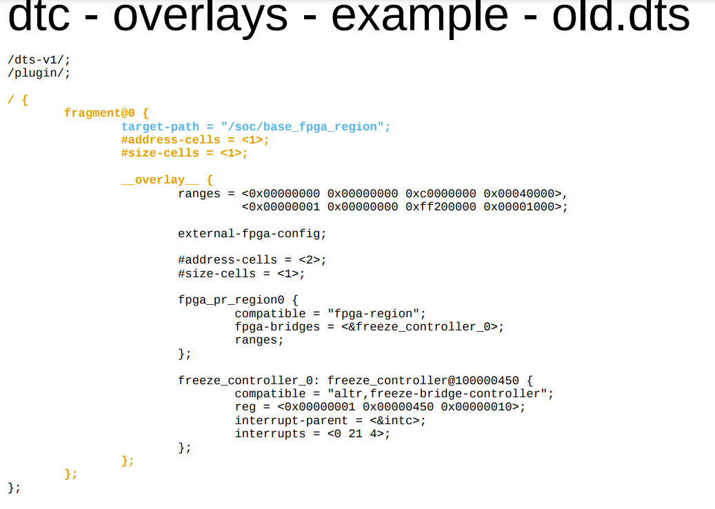
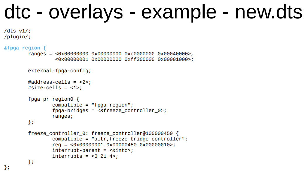
Sugar syntax overlay support in DTG
Customer shouldCustomer should migrate the DTG dtsi files from fragment overlays to sugar syntax.
With sugar syntax, the syntax used by an overlay is now compatible with the syntax used by an
include file, if the include file uses labels as paths instead of using explicit paths.
Release Notes
- 2016.4 DTG Release Notes
- http://www.wiki.xilinx.com/2017.3+Linux+and+DTG+Release+Notes
- http://www.wiki.xilinx.com/2017.4+Linux+and+DTG+Release+Notes
- http://www.wiki.xilinx.com/2018.1+Linux+and+DTG+Release+Notes
- http://www.wiki.xilinx.com/2018.2+Linux+and+DTG+Release+Notes
- 2018.3 Release Notes for Open Source Components (see DTG section)
- 2022.1 Release Notes for Open Source Components (see DTG section)
Build Steps
-
Fetch Sources
- Build FSBL
- Build Device Tree Compiler (DTC)
- Build PMU Firmware
- Build Arm Trusted Firmware (ATF)
- Build U-Boot
- Build and Modify a Root File System
- (You are here) Build Device Tree Blob
- Build Linux Kernel
- Prepare Boot Image
- Prepare Boot Medium
- Setup a Serial Console
- Additional Information: Build Qt and Qwt Libraries
-
Install Xilinx tools
- Build U-Boot
- Build Linux Kernel
- Updated device tree specification can be found here https://www.devicetree.org/
- https://elinux.org/Device_Tree_Usage
Install
-
All systems -
curl cmd.cat/dtc.sh -
Debian
Debian
-
apt-get install device-tree-compiler -
Ubuntu -
apt-get install device-tree-compiler - Alpine
-
apk add dtc -
Arch
Arch Linux
-
pacman -S dtc -
image/svg+xml
Kali Linux
-
apt-get install device-tree-compiler -
CentOS -
yum install dtc -
Fedora -
dnf install dtc -
Windows (WSL2) -
sudo apt-get update
sudo apt-get install device-tree-compiler -
OS X -
brew install dtc -
Raspbian -
apt-get install device-tree-compiler -
Dockerfile -
dockerfile.run/dtc
-
Docker -
docker run cmd.cat/dtc dtc
powered by Commando
device-tree-compiler
Device Tree Compiler for Flat Device Trees
Device Tree Compiler, dtc, takes as input a device-tree in a given format and outputs a device-tree in another format for booting kernels on embedded systems. Typically, the input format is «dts», a human readable source format, and creates a «dtb», or binary format as output.
dtc
Device Tree Compiler
device-tree-compiler-1.4.2
Device Tree Compiler for Flat Device Trees
Device Tree Compiler, dtc, takes as input a device-tree in a given format and outputs a device-tree in another format for booting kernels on embedded systems. Typically, the input format is «dts», a human readable source format, and creates a «dtb», or binary format as output.