
Пройдите тест, узнайте какой профессии подходите
Работать самостоятельно и не зависеть от других
Работать в команде и рассчитывать на помощь коллег
Организовывать и контролировать процесс работы
Введение в рисование на форме в Windows Forms
Рисование на форме в Windows Forms предоставляет разработчикам мощный инструмент для создания графических элементов, таких как линии, прямоугольники, эллипсы и изображения, прямо на поверхности формы. Это может быть полезно для создания пользовательских интерфейсов, визуализации данных или просто для добавления декоративных элементов в ваше приложение. В этой статье мы рассмотрим основные принципы рисования на форме в Windows Forms с использованием языка программирования C#. Мы подробно разберем, как использовать класс Graphics для рисования различных примитивов и изображений, а также рассмотрим некоторые полезные советы и трюки, которые помогут вам в работе.

Создание проекта Windows Forms в Visual Studio
Для начала работы нам потребуется создать проект Windows Forms в Visual Studio. Следуйте этим шагам:
- Откройте Visual Studio и выберите Создать новый проект.
- В списке шаблонов выберите Приложение Windows Forms (.NET Framework).
- Укажите имя проекта и выберите расположение для его сохранения.
- Нажмите Создать.
После создания проекта у вас будет форма, на которой мы будем рисовать. Важно отметить, что Visual Studio предоставляет множество инструментов для упрощения разработки приложений Windows Forms, таких как дизайнер форм, который позволяет визуально добавлять и настраивать элементы управления.
Основы работы с классом Graphics
Для рисования на форме в Windows Forms используется класс Graphics. Этот класс предоставляет методы для рисования различных графических примитивов и изображений. Чтобы начать рисование, нам нужно получить объект Graphics, связанный с формой. Это можно сделать в обработчике события Paint формы. Событие Paint вызывается каждый раз, когда форма перерисовывается, что делает его идеальным местом для выполнения всех операций рисования.
Пример кода для получения объекта Graphics и рисования на форме:
Объект Graphics предоставляет множество методов для рисования различных графических примитивов, таких как линии, прямоугольники, эллипсы и изображения. Важно понимать, что все операции рисования должны выполняться в контексте события Paint, чтобы гарантировать правильное отображение графики на форме.
Примеры рисования примитивов
Линии
Для рисования линий используется метод DrawLine. Этот метод принимает объект Pen, который определяет цвет и толщину линии, а также координаты начальной и конечной точек линии. Пример кода:
Прямоугольники
Для рисования прямоугольников используется метод DrawRectangle. Этот метод также принимает объект Pen, а также координаты верхнего левого угла и размеры прямоугольника. Пример кода:
Эллипсы
Для рисования эллипсов используется метод DrawEllipse. Этот метод принимает объект Pen, а также координаты верхнего левого угла и размеры прямоугольника, в который вписан эллипс. Пример кода:
Использование метода DrawImage для работы с изображениями
Метод DrawImage позволяет рисовать изображения на форме. Для этого сначала нужно загрузить изображение в объект Image, а затем использовать метод DrawImage для его отображения. Метод DrawImage предоставляет множество перегрузок, которые позволяют рисовать изображения с различными параметрами, такими как масштабирование и обрезка.
Пример кода для загрузки и отображения изображения:
Также можно масштабировать изображение при рисовании. Это может быть полезно, если вам нужно изменить размер изображения для его отображения на форме:
Дополнительные советы и трюки
Использование буферизации для улучшения производительности
При рисовании сложных графических элементов на форме может возникнуть проблема мерцания. Это происходит из-за того, что форма перерисовывается слишком часто. Чтобы избежать этого, можно использовать двойную буферизацию. Двойная буферизация позволяет сначала рисовать все элементы на скрытой поверхности, а затем отображать их на форме одним кадром, что значительно уменьшает мерцание.
Для включения двойной буферизации можно установить свойство DoubleBuffered формы в true:
Обработка событий мыши для интерактивного рисования
Вы можете сделать ваше приложение более интерактивным, обрабатывая события мыши для рисования на форме. Например, вы можете рисовать линии или другие примитивы в ответ на движение мыши или нажатие кнопок мыши. Для этого нужно подписаться на соответствующие события формы, такие как MouseDown, MouseMove и MouseUp.
Пример кода для рисования линии при перемещении мыши:
Теперь вы знаете основные методы рисования на форме в Windows Forms. Используя эти знания, вы можете создавать разнообразные графические элементы в своих приложениях. Удачи в ваших начинаниях! 😉
Читайте также
Sign in to your MUO account

Windows Forms is a framework that lets you build desktop applications. You can click and drag components like buttons onto a visual user interface. It also helps you manually create various shapes within your code.
This article will show you how to add lines, shapes, and images to your application. This tutorial uses the Visual Studio 2019 Community Edition to show examples.
What Are the Built-In Classes Used for Drawing Graphics?
Windows Forms uses the C# programming language. Its built-in classes and methods allow you to draw various shapes onto a Windows Form canvas. These include the Graphics, Pen, Color, and Brush classes.
|
Class |
Description |
|---|---|
|
Graphics |
The Graphics class allows you to draw shapes and lines onto the canvas. It includes methods such as:
|
|
Pen |
The Pen class allows you to specify the properties of a ‘pen’ tip which you can use to draw your shapes. You can specify properties such as color, thickness, or dash style. Methods include:
|
|
Color |
A color object made up of R (red), G (green), and B (blue) values. You will need a color object for many of the built-in methods that create shapes. |
|
SolidBrush, HatchBrush, TextureBrush |
These brush classes derive from the «Brush» interface. These classes allow you to color in blank spaces on the canvas. You can also choose to fill the spaces using different patterns or textures. You can specify properties such as the color. |
|
Rectangle, Line, Polygon, Ellipse |
You can create objects based on these shapes, and use them when calling methods such as DrawRectangle(). Instead of passing the x, y, width, and height as arguments, you can choose to pass an existing Rectangle object instead. |
To view the source code for a running example of the above tutorial, visit the GitHub repository. You can try out the following examples once you’ve created a Winforms application.
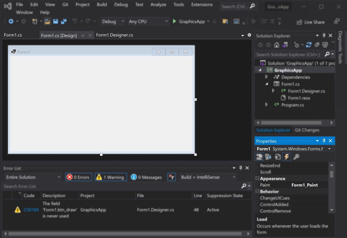
How to Add a Paint on Form Load Event Handler
First, add an event handler to draw shapes when the canvas loads.
-
Add a Paint function for the form.
        private void Form1_Paint(object sender, PaintEventArgs e)
{
    // Code goes here
} - Go into the Design View Tab.
- In the Properties window, select the lightning icon to open the «Events» tab.
-
In «Paint», under «Appearance», select the Form1_Paint function. This will execute the function when you run the application.

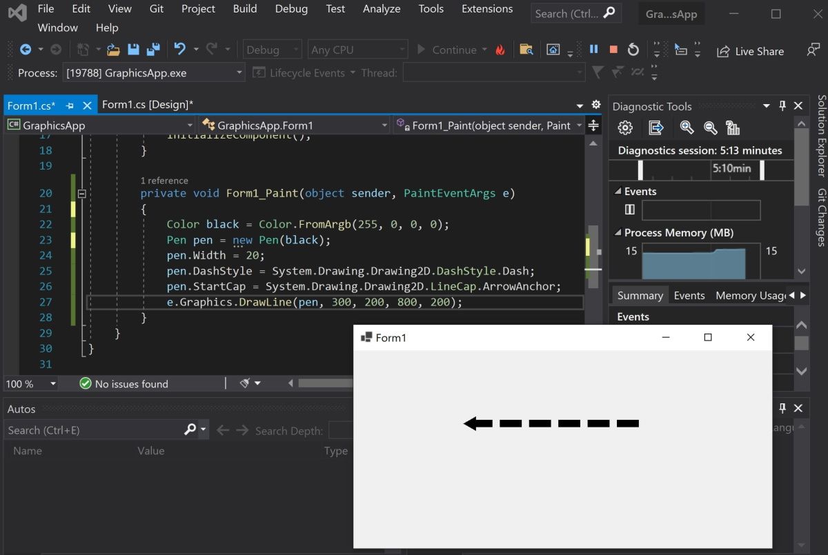
How to Draw Lines Onto a Windows Form Canvas
You can use a Color, Pen, and the DrawLine() method to draw lines on a canvas.
-
Inside the Form1_Paint() function, create a Color object with the color you want the line to be. Then, create a Pen object to draw the line with.
        Color black = Color.FromArgb(255, 0, 0, 0);
Pen blackPen = new Pen(black); -
The DrawLine() method from the Graphics class will draw a line using the pen. This will start drawing a line from an x, y position to another x, y position.
e.Graphics.DrawLine(blackPen, 300, 200, 800, 200); -
You can modify the properties for the pen object to change its width, dash style, and start or end cap.
        blackPen.Width = 20;
blackPen.DashStyle = System.Drawing.Drawing2D.DashStyle.Dash;
blackPen.StartCap = System.Drawing.Drawing2D.LineCap.ArrowAnchor;
e.Graphics.DrawLine(blackPen, 300, 200, 800, 200); -
Press the green play button at the top of Visual Studio to see the changes.

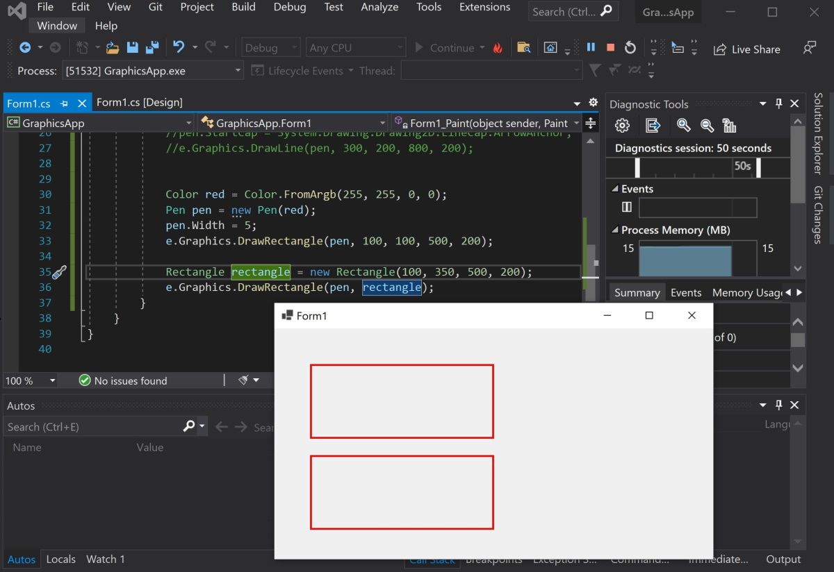
How to Draw Shapes Such as Rectangles and Circles
You can use the shapes classes for different shapes, or draw shapes manually onto the canvas.
-
Create a Color and Pen object as shown in the previous steps. Then, use the DrawRectangle() method to create the rectangle. The arguments are the x and y coordinates for the top-left of the rectangle, along with its width and height.
        Color red = Color.FromArgb(255, 255, 0, 0);
Pen redPen = new Pen(red);
redPen.Width = 5;
e.Graphics.DrawRectangle(redPen, 100, 100, 500, 200); -
You can also create a rectangle using the Rectangle Class. First, create a Rectangle object. The arguments are also the x and y coordinates for the top-left corner, width, and height.
Rectangle rectangle = new Rectangle(100, 350, 500, 200); -
Use the DrawRectangle() function to draw the rectangle. Instead of passing the x, y, width, and height like before, you can use the Rectangle object instead.
e.Graphics.DrawRectangle(redPen, rectangle); -
Press the green play button at the top of Visual Studio to see the changes.

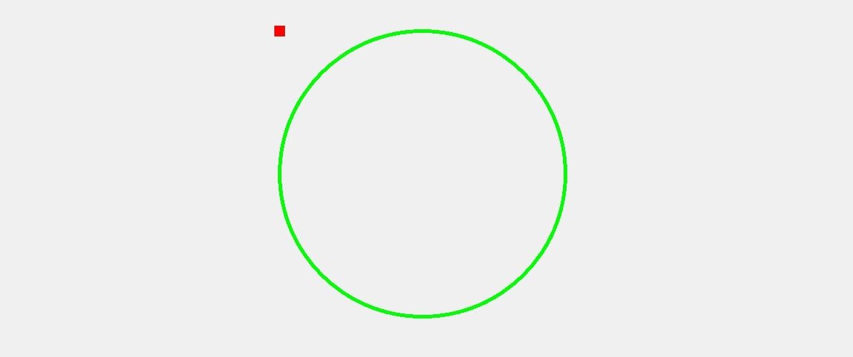
-
Go back to the code to draw other shapes. Use the DrawEllipse() function to draw a circle.
        Color green = Color.FromArgb(255, 0, 255, 0);
Pen greenPen = new Pen(green);
greenPen.Width = 5;
e.Graphics.DrawEllipse(greenPen, 400, 150, 400, 400);
When you draw a circle, the x and y coordinates (x=400, y=150) refer to the top-left corner of the circle, not the center of the circle.

-
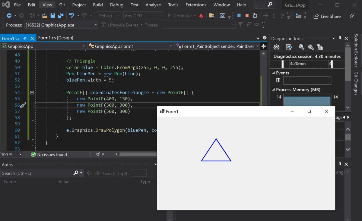
To draw other shapes such as triangles or hexagons, use the DrawPolygon() method. Here you can specify a list of coordinates to represent the points of the shape.
        Color blue = Color.FromArgb(255, 0, 0, 255);
Pen bluePen = new Pen(blue);
bluePen.Width = 5;PointF[] coordinatesForTriangle = new PointF[] {
    new PointF(400, 150),
    new PointF(300, 300),
    new PointF(500, 300)
};e.Graphics.DrawPolygon(bluePen, coordinatesForTriangle);
The DrawPolygon() method will draw lines between the points specified.

How to Use the Brush Class to Fill In Shapes With Color
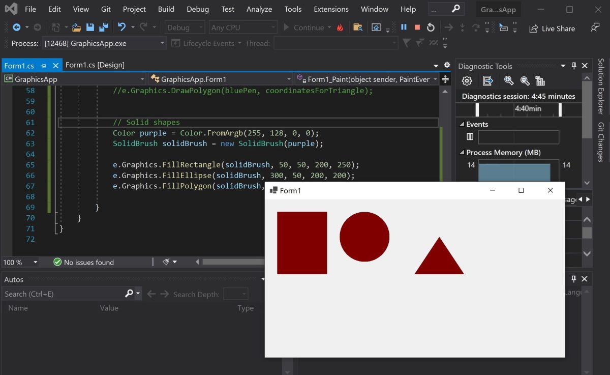
You can use the FillRectangle(), FillEllipses() or FillTriangle() methods to create shapes with a solid color.
-
First, create a brush object.
        Color purple = Color.FromArgb(255, 128, 0, 0);
SolidBrush solidBrush = new SolidBrush(purple); -
Use the FillRectangle(), FillEllipses() or FillTriangle() methods. They work the same way as the draw functions above, except instead of a Pen, they use a Brush object.
        e.Graphics.FillRectangle(solidBrush, 50, 50, 200, 250);
e.Graphics.FillEllipse(solidBrush, 300, 50, 200, 200);
e.Graphics.FillPolygon(solidBrush, new PointF[] { new PointF(700, 150), new PointF(600, 300), new PointF(800, 300) });
-
You can also input a shape object directly instead of providing coordinates.
        Rectangle rectangle = new Rectangle(100, 350, 500, 200);
e.Graphics.FillRectangle(solidBrush, rectangle); -
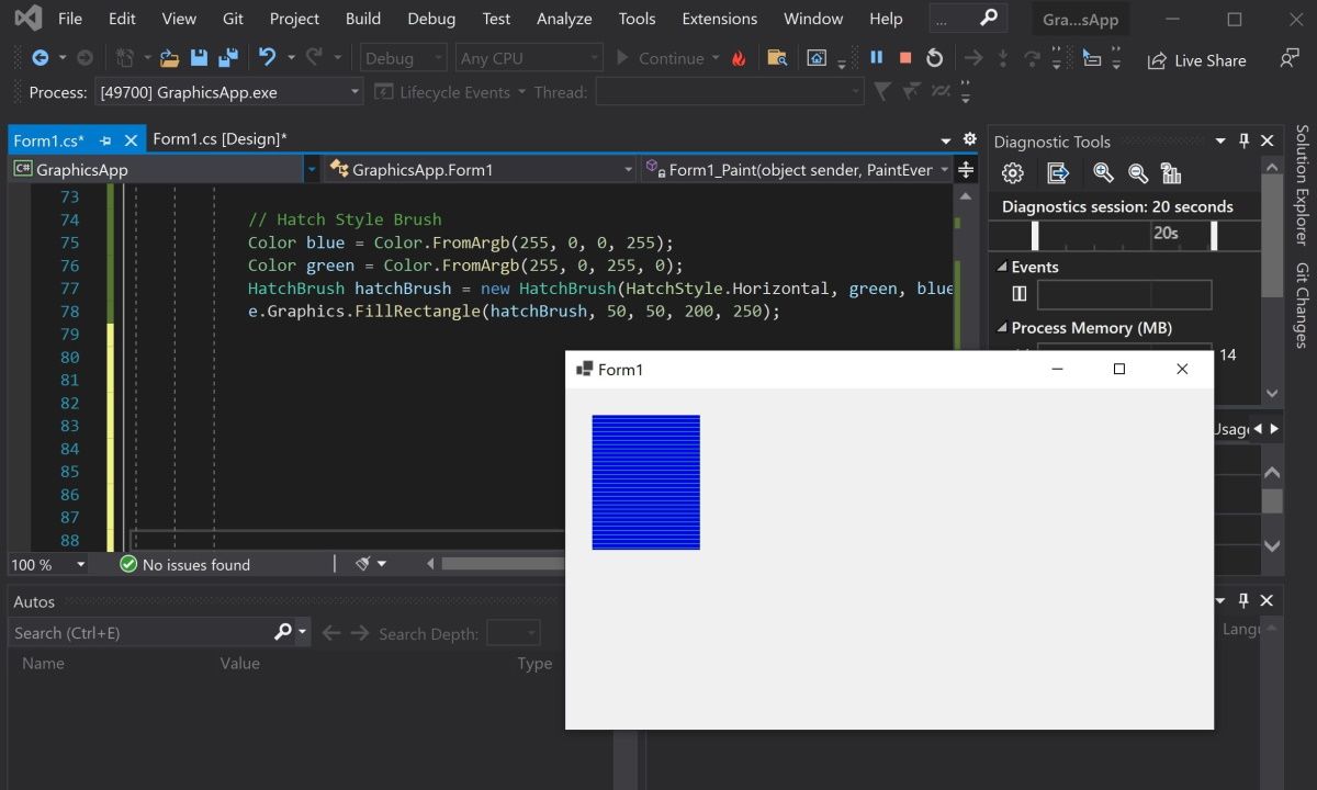
Use the HatchBrush to fill the shape using a different fill style, such as a horizontal or vertical pattern.
        Color blue = Color.FromArgb(255, 0, 0, 255);
Color green = Color.FromArgb(255, 0, 255, 0);
HatchBrush hatchBrush = new HatchBrush(HatchStyle.Horizontal, green, blue);
e.Graphics.FillRectangle(hatchBrush, 50, 50, 200, 250);
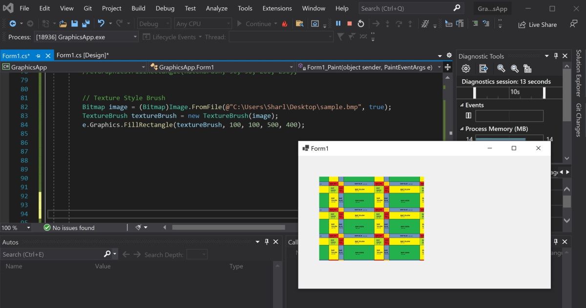
-
You can use the TextureBrush to fill a shape using an image. Here, create a bitmap by pointing to an image file. Instead of creating a brush using a color, create it using the image.
        Bitmap image = (Bitmap)Image.FromFile(@"C:\Users\Sharl\Desktop\flag.bmp", true);
TextureBrush textureBrush = new TextureBrush(image);
e.Graphics.FillRectangle(textureBrush, 100, 100, 500, 400);
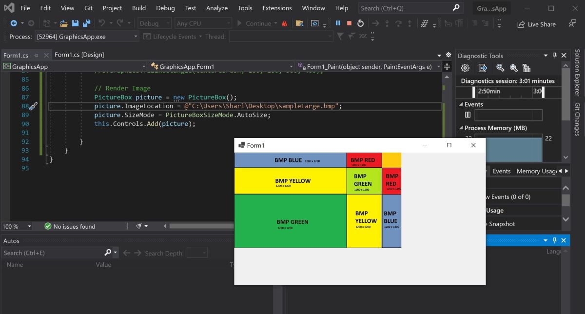
How to Render Images Onto the Form
To render an image, create a PictureBox control object and add it to the form.
-
Create a PictureBox control object using an image file.
        PictureBox picture = new PictureBox();
picture.ImageLocation = @"C:\Users\Sharl\Desktop\flagLarge.bmp"; -
Set the size of the image and add it onto the form so it renders.
        picture.SizeMode = PictureBoxSizeMode.AutoSize;
this.Controls.Add(picture); -
Press the green start button at the top to view the image.

Adding More Shapes to Your Windows Form
You should now understand how to add lines, shapes, and images to your Windows form. You can combine shapes to create new shapes. You can also play around with the built-in functions to create more complex shapes.
C#: работаем с графикой и графическими компонентами в приложениях Windows Forms
Для работы с изображениями в библиотеке .NET определён базовый класс System.Drawing.Image, который предоставляет функциональные возможности для производных классов System.Drawing.Bitmap (растровая графика) и System.Drawing.MetaFile (векторная графика). Этот класс содержит методы для создания (и сохранения) объектов типа Image из указанного файла, потока данных и т.д.
Когда требуется перерисовка элемента управления, происходит событие Paint, которое, в зависимости от задачи, можно как программировать явно, так и полагаться на его автоматический вызов, происходящий, когда изменилась графическая канва объекта.
Для отрисовки готового файла с изображением, имя которого задано или получено из диалога открытия файла OpenFileDialog, мы должны создать или получить из аргумента PaintEventArgs метода Paint графическую канву типа System.Drawing.Graphics а затем уже вывести на неё изображение.
Графическая канва позволяет посредством инструментов типов Pen (перо), Brush (кисть) и других работать с методами рисования контурных и залитых цветом геометрических примитивов, имена первых начинаются префиксом «Draw», а вторых «Fill». При этом код отрисовки не будет меняться в зависимости от того, создана графика для поверхности формы методом CreateGraphics или получена из изображения с помощью метода FromImage.
Для использования готовых методов обработки изображений (поворот, масштабирование, изменение цвета и т.п.) мы программно создаём объект типа System.Drawing.Bitmap, копирующий имеющееся изображение, выполняем его обработку, а затем выводим изменённый объект в компоненту, предназначенную для отображения, такую как PictureBox.
Проект Lab5_1. Выведем выбранный в стандартном диалоге открытия файла рисунок на форму (пункт меню Файл — Открыть) и принудительно перерисуем по пункту меню Правка — Перерисовать. В свойствах диалога открытия файла openFileDialog1 указано Filter = Все файлы|*.*|Рисунки BMP|*.bmp|Рисунки JPEG|*.jpg|Рисунки PNG|*.png а свойство FileName равно пустой строке.
В классе формы пропишем объекты «Изображение» и «Имя файла»:
private Image Img;
private String Name;
Напишем обработчик открытия файла:
   //Обработка меню Файл - Открыть
   openFileDialog1.ShowDialog();
   Name = openFileDialog1.FileName.Trim();
   if (String.IsNullOrEmpty(Name)) return;
   try {
    Img = new Bitmap(Name);
    //или так: Img = Image.FromFile(Name);
   }
   catch (Exception ex) {
    MessageBox.Show(ex.Message + Environment.NewLine + "(не могу открыть файл)",
     "Ошибка", MessageBoxButtons.OK, MessageBoxIcon.Exclamation);
    toolStripLabel1.Text = "Файл не выбран";
    Img = null;
    return;
   }
   this.ClientSize = new System.Drawing.Size(Img.Width, Img.Height);
    //Размер формы подгогнали под размер картинки
   toolStripLabel1.Text = Name;
    //Имя файла вывели в панель инструментов
   this.Refresh(); //Потребовать перерисовки!
По событию Paint формы будет выполняться отрисовка объекта Img на текущей канве, Y-координата для вставки рисунка учитывает пространство, занимаемое по вертикали компонентами menuStrip1 и toolStripLabel1:
  private void Form1_Paint(object sender, PaintEventArgs e) {
   if (Img != null) {
    Point p = new Point(0, menuStrip1.Size.Height+ toolStripLabel1.Size.Height);
    e.Graphics.DrawImage(Img, p);
   }
  }
Объект «Графика», представляющий собой поверхность для рисования, также может быть получен для канвы формы (вот обработчик пункта меню Правка — Перерисовать):
   if (Img != null) {
    Graphics g = this.CreateGraphics();
    Point p = new Point(0, menuStrip1.Size.Height + toolStripLabel1.Size.Height);
    g.DrawImage(Img, p);
   }
или из загруженного (сгенерированного) изображения, например, см. код для пункта меню Файл — Создать:
   Img = new Bitmap(200, 200,
    System.Drawing.Imaging.PixelFormat.Format24bppRgb);
   Graphics Gr = Graphics.FromImage(Img);
   // Теперь становятся доступными методы класса Graphics!
   Pen pen = new Pen(Color.ForestGreen, 4.0F);
   Gr.DrawLine(pen, 0, 0, 199, 199);
   Gr.RotateTransform(180.0F); //поворот на 180 градусов
   Img.Save("example.jpg", System.Drawing.Imaging.ImageFormat.Jpeg); //сохранение
   this.Refresh();
Обычно рисунки не отображают на канве формы, а работают с компонентом PictureBox (вкладка Стандартные), представляющим собой контейнер для размещения рисунка, вот его основные свойства:
Image— рисунок. Само изображение можно загрузить программно через свойствоImageLocation, например, в методеLoadформы:openFileDialog1.ShowDialog(); if (openFileDialog1.FileName != null) this.pictureBox1.ImageLocation = this.openFileDialog1.FileName;
или же присвоить этому свойству объект
Image, как мы делали выше.SizeMode— режим вывода:Normal— по левому верхнему углу контейнера с обрезанием,StretchImage— вписать в компонент,AutoSize— компонент примет размеры изображения,CenterImage— центрировать, не меняя размеры (может обрезать рисунок),Zoom— пропорционально масштабировать по размерам компонента (пространство именPictureBoxSizeMode).
Для возможности прокрутки загруженного изображения достаточно разместить PictureBox на элементе Panel с установленными свойствами AutoScroll = true, Location = 0;0 (и Dock = Fill, если панель должна занимать всю клиентскую часть окна) и при этом для PictureBox указать SizeMode = AutoSize. После этого можно загрузить рисунок кодом вида
Image Img = new Bitmap(openFileDialog1.FileName);
pictureBox1.Image = Img;
ErrorImage— позволяет задать изображение, выводимое при ошибке загрузки;InitialImage— позволяет задать изображение, выводимое в процессе загрузки.
К другим полезным компонентам можно отнести:
ImageList(вкладка Компоненты) — список изображений, который можно использовать для «прокрутки» картинок или как список иконок для меню, вкладок и т.п.Timer(вкладка Компоненты), позволяет обрабатывать периодическое событиеTickи организовывать смену картинок в реальном времени, частота повторения события в миллисекундах задаётся свойствомInterval.
Мы используем их в следующей теме.
Скачать пример Lab5_1 в архиве .zip с проектом C# Visual Studio 2019 (12 Кб)
Проект Lab5_2. Основные операции над изображениями. Кроме pictureBox1, размещённого на Panel как описано выше, форма включает в себя стандартный диалог открытия файла openFileDialog1, меню Файл — Открыть (обработчик аналогичен предыдущему примеру) и меню «Правка», откуда мы будем вызывать обработчики загруженного изображения.
5.2.1. Поворот и отражение изображений. В этом примере выведенный в PictureBox рисунок поворачивается на 180 градусов и выводится обратно в PictureBox:
   if (pictureBox1.Image != null) {
    Bitmap bitmap1 = new Bitmap(pictureBox1.Image);
    if (bitmap1 != null) {
     bitmap1.RotateFlip(RotateFlipType.Rotate180FlipY);
     pictureBox1.Image = bitmap1;
    }
   }
Остальные повороты (отражения) – другие значения параметра RotateFlipType.
5.2.2. Масштабирование изображения или его части. Код ниже показывает, как можно программно уменьшить загруженное в компоненту PictureBox изображение в 2 раза:
   if (pictureBox1.Image == null) return;
   Bitmap  bitmap1 = new Bitmap (pictureBox1.Image); //взяли рисунок из компоненты
   Graphics  Gr1 = Graphics.FromImage (bitmap1);
    //получили поверхность рисования из исходного рисунка
   Bitmap  bitmap2 = new Bitmap (bitmap1.Width / 2, bitmap1.Height / 2, Gr1);
    //сделали вдвое меньший рисунок с тем же разрешением
   Graphics  Gr2 = Graphics.FromImage (bitmap2);
    //получили поверхность рисования из меньшего рисунка
   Rectangle compressionRectangle = new Rectangle
     (0, 0, bitmap1.Width / 2, bitmap1.Height / 2); //определили масштабирующий прямоугольник
   Gr2.DrawImage (bitmap1, compressionRectangle);
    //отрисовали на поверхности второго рисунка первый со сжатием
   Pen  MyPen = new Pen (Color.Red); //на измененном рисунке можно что-то подрисовать
   Gr2.DrawRectangle (MyPen, 0, 0, bitmap2.Width - 1, bitmap2.Height - 1);
    //например, сделать красную рамку
   pictureBox1.Image = bitmap2; //назначили второй рисунок компоненте
   pictureBox1.Size = bitmap2.Size; //поставили размер компоненты по размерам нового рисунка
   this.ClientSize = pictureBox1.Size; //...и такой же размер клиентской формы
Добавим пункт меню Файл — Сохранить и сохраним изображение:
   if (pictureBox1.Image == null) return;
   Bitmap bitmap1 = new Bitmap (pictureBox1.Image);
   try {
    bitmap1.Save (openFileDialog1.FileName);
     //Сохраняем под именем из диалога открытия файла
     //Может вызвать исключение, если исходный файл ещё открыт
   }
   catch (Exception ex) {
    MessageBox.Show (ex.Message + "\nНе удалось сохранить файл",
      "Ошибка", MessageBoxButtons.OK, MessageBoxIcon.Exclamation);
    return;
   }
Как вариант:
pictureBox1.Image.Save (openFileDialog1.FileName);
К сожалению, этот код может вызвать исключение, если исходный файл ещё открыт. Для «надёжных» операций с файлами при открытии изображений используйте FileStream, чтобы контролировать весь процесс (перепишем обработчик пункта меню «Открыть»):
   openFileDialog1.ShowDialog ();
   if (openFileDialog1.FileName.Trim () != "" && openFileDialog1.FileName != null) {
    System.IO.FileStream file;
    try {
     file = new System.IO.FileStream (openFileDialog1.FileName, System.IO.FileMode.Open,
       System.IO.FileAccess.Read, System.IO.FileShare.Inheritable);
    }
    catch (Exception ex) {
     MessageBox.Show (ex.Message + "\nНе удалось открыть файл", "Ошибка",
      MessageBoxButtons.OK, MessageBoxIcon.Exclamation);
     return;
    }
    pictureBox1.Image = Image.FromStream (file);
    file.Close ();
   }
5.2.3. Изменение цвета на изображении. На форму добавлен стандартный СolorDialog и выбранный в нём цвет ставится прозрачным.
   if (pictureBox1.Image == null) return;
   Bitmap bitmap1 = new Bitmap (pictureBox1.Image);
   if (colorDialog1.ShowDialog () == DialogResult.OK) {
    bitmap1.MakeTransparent (colorDialog1.Color);
    pictureBox1.Image = bitmap1;
   }
5.2.4. Фильтрация всего изображения или его части (по пикселям). В качестве примера уменьшим вдвое интенсивность синего цвета на картинке, избегая пикселей, цвет которых близок к белому (интенсивности красной, зелёной и синей компонент больше значения 250):
   if (pictureBox1.Image == null) return;
   Bitmap bitmap1 = new Bitmap (pictureBox1.Image);
   for (int x = 0; x < bitmap1.Width; x++)
    for (int y = 0; y < bitmap1.Height; y++) {
     Color pixelColor = bitmap1.GetPixel (x, y);
     if (pixelColor.R > 250 && pixelColor.G > 250 && pixelColor.B > 250)
      continue; //не фильтруем пиксели, чей цвет близок к белому
     Color newColor = Color.FromArgb (pixelColor.R, pixelColor.G, pixelColor.B / 2);
     bitmap1.SetPixel (x, y, newColor);
    }
   pictureBox1.Image = bitmap1;
Аналогично можно реализовать любую другую фильтрацию цветов, но из-за «ручного» прохода по пикселям скорость выполнения процесса может быть заметно ниже, чем для пп. 5.2.1-5.2.3. Более быстрый способ преобразования всех цветов рисунка даёт применение фильтрации на основе класса ColorMatrix. В качестве примера приведём код, преобразующий цветное изображение к оттенкам серого:
   if (pictureBox1.Image == null) return;
   Bitmap bitmap1 = new Bitmap (pictureBox1.Image);
   Bitmap bitmap2 = new Bitmap (bitmap1.Width, bitmap1.Height);
   Graphics g = Graphics.FromImage (bitmap2);
   float [] [] Map = {
    new float[] {0.30f, 0.30f, 0.30f, 0.00f, 0.00f },
    new float[] {0.59f, 0.59f, 0.59f, 0.00f, 0.00f },
    new float[] {0.11f, 0.11f, 0.11f, 0.00f, 0.00f },
    new float[] {0.00f, 0.00f, 0.00f, 1.00f, 0.00f },
    new float[] {0.00f, 0.00f, 0.00f, 0.00f, 1.00f }
   };
   System.Drawing.Imaging.ColorMatrix GrayscaleMatrix =
    new System.Drawing.Imaging.ColorMatrix (Map);
   System.Drawing.Imaging.ImageAttributes attributes =
    new System.Drawing.Imaging.ImageAttributes ();
   attributes.SetColorMatrix (GrayscaleMatrix);
   Rectangle rect = new Rectangle (0, 0, bitmap1.Width, bitmap1.Height);
   g.DrawImage (bitmap1, rect, 0, 0, bitmap1.Width, bitmap1.Height,
    GraphicsUnit.Pixel, attributes);
   pictureBox1.Image = bitmap2;
О классе ColorMatrix можно почитать, например, по ссылке. В нашем фильтре соотношение «весов» красной, зелёной и синей цветовых компонент 0.3 — 0.59 — 0.11 отражает чувствительность человеческого глаза к оттенкам красного, зелёного и синего.
В некоторых случаях фильтровать изображения можно и сменой свойства Image.PixelFormat, но вариант Format16bppGrayScale в GDI+ не сработал.
5.2.5. Сохранить рисунок так, как он выглядит на компоненте. Следует понимать, что свойство SizeMode управляет отображением рисунка в компоненте, при сохранении пропорции рисунка не изменятся от того, что он был выведен, например, при SizeMode=StretchImage (принудительно растянут по размерам компоненты, возможно, с нарушением пропорций). Тем не менее — а можно ли сохранить рисунок так, как он был выведен в компоненту? Да, можно, например, так:
   if (pictureBox1.Image == null) return;
   pictureBox1.SizeMode = PictureBoxSizeMode.StretchImage;
   pictureBox1.Dock = DockStyle.Fill; //установили растягивание
   Bitmap bitmap1 = new Bitmap (pictureBox1.Image);
   Bitmap bitmap2 = new Bitmap (pictureBox1.Width, pictureBox1.Height);
    //у 2-го рисунка - размер компоненты
   Graphics g = Graphics.FromImage (bitmap2);
    //получили графический контекст из 2-го рисунка
   g.InterpolationMode = System.Drawing.Drawing2D.InterpolationMode.Bicubic;
    //настроили режим интерполяции
   g.DrawImage (bitmap1, new Rectangle(0,0, bitmap2.Width, bitmap2.Height));
    //отрисовали в контекст 2-го рисунка исходный, неискажённый рисунок
   pictureBox1.Image = bitmap2; //назначили искажённый рисунок компоненте
   сохранитьToolStripMenuItem_Click (this, e); //вызвали метод сохранения
   pictureBox1.SizeMode = PictureBoxSizeMode.AutoSize;
   pictureBox1.Dock = DockStyle.None; //восстановили свойства
   pictureBox1.Image = bitmap1; //вернули старый рисунок
Убедиться в том, что рисунок был пересохранён в фоновом режиме с размерами, соответствующими клиентской части формы можно, заново открыв его с диска.
5.2.6. Выделить часть рисунка и реализовать обрезку по выделенной области. В класс формы добавим следующие глобальные данные:
  Rectangle selRect; //выделенный прямоугольник
  Point orig; //точка для привязки прямоугольника
  Pen pen; //перо для отрисовки
  bool flag; //флажок показывает, находимся ли в режиме выделения части рисунка
Инициализируем их, например, в имеющемся конструкторе формы:
  public Form1() {
   InitializeComponent();
   pen = new Pen (Brushes.Blue, 0.8f); //цвет и толщина линии выделения
   pen.DashStyle = System.Drawing.Drawing2D.DashStyle.Dash; //штрихи
   selRect = new Rectangle (0, 0, 0, 0);
   flag = false;
  }
Реализация динамического выделения мышью потребует взаимодействия нескольких событий (нажатие кнопки мыши, отпускание кнопки мыши и перемещение мыши). Для удобства используем также динамическое переключение обработчика события Paint (чтобы рисовать рамку выделения только тогда, когда она нужна – происходит перемещение курсора мыши на pictureBox при зажатой левой кнопке).
  private void pictureBox1_Paint (object sender, PaintEventArgs e) {
   //Этот обработчик мы создали в конструкторе
   //Для ситуации, когда выделяем рамку
   e.Graphics.DrawRectangle (Pens.Black, selRect);
  }
  private void Selection_Paint (object sender, PaintEventArgs  e) {
   //Добавили свой обработчик Paint для остальных ситуаций
   e.Graphics.DrawRectangle (pen, selRect);
  }

  private void pictureBox1_MouseDown (object sender, MouseEventArgs e) {
   //Этот обработчик мы создали в конструкторе
   //Нажали мышку - включаем наш обработчик и выключаем стандартный
   pictureBox1.Paint -= new PaintEventHandler (pictureBox1_Paint);
   pictureBox1.Paint += new PaintEventHandler (Selection_Paint);
   orig = e.Location; //запомнили, где начало выделения
   flag = true;
  }

  private void pictureBox1_MouseUp (object sender, MouseEventArgs e) {
   //Этот обработчик мы создали в конструкторе
   //отжали мышку - всё наоборот
   pictureBox1.Paint -= new PaintEventHandler (Selection_Paint);
   pictureBox1.Paint += new PaintEventHandler (pictureBox1_Paint);
   pictureBox1.Invalidate (); //принудительно перерисовать
   flag = false; //выйти из режима выделения
  }

  private void pictureBox1_MouseMove (object sender, MouseEventArgs e) {
   //Этот обработчик мы создали в конструкторе
   if (flag) { //если в режиме выделения
    selRect = GetSelectionRectangle (orig, e.Location); //запоминаем выделенное
    if (e.Button == MouseButtons.Left) {
     pictureBox1.Refresh (); //рефрешим картинку по нажатию левой кнопки
    }
   }
  }

  private Rectangle GetSelectionRectangle (Point orig, Point location) {
   //Этот метод пришлось написать, чтобы координаты выделения правильно запоминались
   //независимо от того, в какую сторону тащим курсор мыши
   Rectangle rect = new Rectangle ();
   int dX = location.X - orig.X, dY = location.Y - orig.Y;
   System.Drawing.Size size = new System.Drawing.Size (Math.Abs (dX), Math.Abs (dY));
    //размеры текущего выделения
   if (dX >= 0 && dY >= 0) rect = new Rectangle (orig, size);
   else if (dX < 0 && dY > 0) rect = new Rectangle (location.X, orig.Y, size.Width, size.Height);
   else if (dX > 0 && dY < 0) rect = new Rectangle (orig.X, location.Y, size.Width, size.Height);
   else rect = new Rectangle (location, size);
   return rect;
  }
Теперь, при наличии на изображении выделенной рамки selRect можно, например, реализовать его обрезание по границам этой рамки:
   if (pictureBox1.Image == null) return;
   if (selRect.Width > 0 && selRect.Height > 0) {
    Bitmap bitmap1 = new Bitmap (pictureBox1.Image);
    Bitmap bitmap2 = new Bitmap (selRect.Width, selRect.Height);
    Graphics g = Graphics.FromImage (bitmap2);
    g.DrawImage (bitmap1, 0, 0, selRect, GraphicsUnit.Pixel);
    pictureBox1.Image = bitmap2;
    selRect = new Rectangle (0, 0, 0, 0);
   }
Скачать пример Lab5_2 в архиве .zip с проектом C# Visual Studio 2019 (14 Кб)
Проект Lab5_3. Рисование фигур. Показанный выше подход нетрудно применить для рисования геометрических примитивов на канве PictureBox или формы.
Создадим форму как в предыдущем примере с PictureBox, расположенным на Panel, у компонент установлены те же свойства (для PictureBox дополнительно укажем Dock = Fill).
Рассмотрим варианты рисования линии на канве PictureBox. При движении мыши с зажатой левой кнопкой наша линия должна динамически обновляться, а при отпускании кнопки — добавляться на существующий рисунок.
Опишем в классе формы необходимые данные:
  Point p1, p2; //начало и конец линии
  Pen pen1; //перо
  Brush brush1; //кисть
  Bitmap Img1, Img2; //основная картинка, на которой рисуем и буферная
  Graphics gr; //графический контекст
  bool isPressed; //флажок "кнопка мыши зажата"
Для самой формы нам понадобится запрограммировать событие Load, где мы инициализируем эти объекты, то есть, создадим рисунок размером с клиентскую часть окна формы, назначим его компоненте, создадим перо и выставим в «ложь» флажок:
   Img1 = new Bitmap (ClientSize.Width, ClientSize.Height);
   pictureBox1.Image = Img1;
   gr = Graphics.FromImage (Img1);
   pen1 = new Pen (Color.Black);
   isPressed = false;
Всё остальное запрограммируем в событиях PictureBox. На нажатие кнопки мыши будем включать флажок и запоминать место клика p1:
  private void pictureBox1_MouseDown (object sender, MouseEventArgs e) {
   isPressed = true;
   p1 = e.Location;
  }
На отпускание кнопки получим координаты второй точки p2 и соединим её с первой, проведя линию на образе Img1. Заметим, что в реальном коде можно добавлять точки в контейнер, например, в список List из объектов Point. Если при этом запоминать, какой именно объект рисовался, можно в нужные моменты просто перерисовывать объекты по списку (что может предотвратить «утечки памяти» при работе приложения), а также удалять или динамически изменять их.
  private void pictureBox1_MouseUp (object sender, MouseEventArgs e) {
   p2 = e.Location;
   gr = Graphics.FromImage (Img1);
   gr.DrawLine (pen1, p1, p2);
   gr.Save ();
   isPressed = false;
   pictureBox1.Invalidate ();
  }
На перемещение мыши обработка будет немного хитрей. Если кнопка не зажата, ничего делать не нужно, а в противном случае будем проводить текущую линию на копии рисунка Img2, созданной из Img1, чтобы не получилось «веера» из линий при перемещении мыши с зажатой кнопкой. Img2 всё равно придётся временно назначить рисунком для PictureBox, чтобы линия была видна в процессе движения мыши.
  private void pictureBox1_MouseMove (object sender, MouseEventArgs e) {
   if (!isPressed) return; //Кнопка не зажата - выйти
   p2 = e.Location;
   Img2 = new Bitmap (Img1);
   pictureBox1.Image = Img2;
   gr = Graphics.FromImage (Img2);
   gr.DrawLine (pen1, p1, p2);
   pictureBox1.Invalidate ();
  }
В показанном примере все координаты отсчитывались «внутри PictureBox» и получались непосредственно из аргумента MouseEventArgs обработчика события. По-другому можно сделать, используя координаты курсора относительно экрана Cursor.Position.X, Cursor.Position.Y, а затем вычитая из них координаты верхнего левого угла формы Location.X, Location.Y (и, возможно, дополнительные значения, учитывающие занятое другими компонентами пространство на форме):
   int x1 = Cursor.Position.X - Location.X,
    y1 = Cursor.Position.Y - Location.Y;
Расположив на панели инструментов приложения дополнительные кнопки для выбора геометрического примитива, цвета и т. п., мы можем получить приложение графический-редактор (см. прикреплённый проект, где ряд возможностей уже добавлен).
Обратите внимание в коде проекта Lab5_3: при рисовании линии и эллипса координаты второй точки могут быть и «меньше» (ближе к левому верхнему углу холста), чем первой. При рисовании же прямоугольника область экрана должна быть задана, начиная с левого верхнего угла. Метод
GetRectangle, вызываемый при обработке событийpictureBox1_MouseUpиpictureBox1_MouseMove, корректирует эту проблему, как и при выделении прямоугольником в проекте Lab5_2.
Скачать пример Lab5_3 в архиве .zip с проектом C# Visual Studio 2019 (19 Кб)

Простая рисовалка на Windows Forms C#
Проект Lab5_4. Другой контекст. В завершение заметим, что отрисовка, выполняемая в объекте графического контекста, позволяет без каких-либо изменений основного кода «перенести» графический объект на другую канву, например, на экран вместо окна приложения.
Пусть в классе формы имеется метод Draw, создающий некоторый рисунок:
  void Draw (System.Drawing.Graphics g) { //Графический контекст передан в наш метод
   Pen [] pens =  { Pens.Red, Pens.Yellow, Pens.Green };
    //Разные перья для рисования
   int width = ( this.ClientSize.Width - 1 ) / 2,
       height = ( this.ClientSize.Height - 1 ) / 2;
    //Половинки ширины и высоты клиентской части окна
   for (int i = 0; i < 3; i++) //Демо - рисуем перьями
    g.DrawRectangle (pens [i], i * width, i * height, width, height);
   Brush [] brushes = { Brushes.Red, Brushes.Yellow, Brushes.Green };
    //Разные кисти для выполнения заливки цветом
   for (int i = 0; i < 3; i++) //Демо - рисуем кистями
    g.FillEllipse (brushes [i], i * width, i * height, width, height);
   g.DrawLine (pens [2], 0, 0, width * 2, height * 2); //Рисуем линию пером
  }
Как и в начале статьи, мы могли бы вызвать его кодом вида
   Graphics g = this.CreateGraphics ();
   Draw (g);
для отображения картинки непосредственно на канве формы.
Теперь выведем рисунок в контексте графического экрана Windows поверх всех окон.
Убедимся, что к файлу формы подключены нужные пространства имён:
using System.Runtime.InteropServices;
using System.Drawing;
В классе формы (например, после конструктора) укажем ссылки на нужные методы библиотеки user32.dll, которые нам потребуются:
  [DllImport ("user32.dll")]
  public static extern IntPtr GetDC (IntPtr hwnd);
  [DllImport ("user32.dll")]
  public static extern void ReleaseDC (IntPtr hwnd, IntPtr dc);
В методе рисования (например, по событию Paint формы) вызовем наш метод с другим контекстом:
  private void Form1_Paint (object sender, PaintEventArgs e) {
   IntPtr desktopPtr = GetDC (IntPtr.Zero);
   Graphics g = Graphics.FromHdc (desktopPtr);

   Draw (g);

   g.Dispose ();
   ReleaseDC (IntPtr.Zero, desktopPtr);
  }
Также можно потребовать где-нибудь принудительной перерисовки, например, по клику на форме:
  private void Form1_Click (object sender, EventArgs e) {
   Invalidate ();
  }
Подключить к проекту внешнюю библиотеку можно и непосредственно, например, для нашего случая:
- в верхнем меню выбрать команду Проект — Добавить существующий элемент…;
- в списке типов файлов выбрать «Исполняемые файлы», показать расположение нужного файла (
c:\Windows\System32\user32.dll) и нажать «Добавить»;- выбрать добавленный файл в Обозревателе решений, в окне «Свойства» указать для него значение «Копировать в выходной каталог» равным «Копировать более новую версию»;
- после этого прототипы нужных функций библиотеки можно описать в классе формы с атрибутами
public static externи предшествующей директивой[DllImport ("user32.dll")], как мы делали выше.
Скачать пример Lab5_4 в архиве .zip с проектом C# Visual Studio 2019 (11 Кб)
Задание по теме может быть, например, таким: реализовать графическое приложение в соответствии с вариантом. Предусмотреть в приложении следующие возможности:
- сохранение полученных графических файлов;
- прокрутка файлов, если они «не помещаются» в окне компоненты
PictureBox; - возможность построить изображение более, чем в одном масштабе (или масштабировать его программно);
- не менее двух настраиваемых параметров, позволяющих изменить внешний вид объекта (например, для объекта «дом» — количество этажей и количество окон на каждом этаже).
05.04.2023, 19:26 [8623 просмотра]
К этой статье пока нет комментариев, Ваш будет первым
The System.Drawing and GDI + package
The System.Drawing package provides access to GDI + Windows features:
- Drawing surfaces
- Working with graphics and graphical transformations
- Drawing geometric shapes
- Working with images
- Working with text and fonts
- Printing on printer
It consists of several spaces:
- System.Drawing — provides basic classes such as surfaces, pencils, brushes, classes for text painting.
- System.Drawing.Imaging — Provides classes for working with images, pictures and icons, classes for converting to different file formats and for resizing images.
- System.Drawing.Drawing2D — Provides classes for graphical transformations — blends, matrixes, and more.
- System.Drawing.Text — Provides classes for accessing the graphical environment fonts.
- System.Drawing.Printeing — Provides printer printing classes and system dialog boxes for printing.
Class Graphics
The System.Drawing.Graphics class provides an abstract drawing surface. Such a surface may be part of the screen control as well as part of a printer page or other device.
The most common drawing is done in the Paint event handler. If necessary, the graphical appearance of the control is redefined. The provided PaintEventArgs parameter contains the Graphics Object. A graphic object can be created using Control.CreateGraphics(). It must necessarily be released through the finally block or using construction because it is a valuable resource.

Coordinate system
The value for x is the location of the point along the x-axis, if x = 0 this means that the point is at the extreme left of the coordinate system.
The value for y is the location of the point on the y-axis, if y = 0 this means that the point is at the top of the coordinate system.
Example:
A starting point and an end point must be available to draw a line. The starting point is set by the values x1 and y1. The endpoint is set by the values of x2 and y2. In this case x1 = y1 = 75 pixels and x2 = y2 = 275 pixels.
To draw figures in C #, a starting point, an end point, and a Pen control must be available.
Pen control in C# Windows Forms
The most important properties of this control are:
- DashStyle — sets the type of line.
- Color — sets the color of the line.
- Width — sets the line width (in pixels).
- Alignment — sets where to position Pen control over the theoretical line.
C# has the ability to draw text as well. The Font and SolidBrush controls are required to draw text.
The main parameters of the Font Class are:
- FontFamily — Sets the font, for example: «Courier New».
- Font size — sets the font size.
- FontStyle — sets the font style, for example: bold.
The main parameters of the SolidBrush class is:
- Color — sets the color of the brush.
Sample tasks
1) Crete application that draws: circle, square, arch, pie, smiley man, figure by set values and text. Draw in two variants: the first one only with Pen controls and the second one with Pen and Brush controls (where possible). The field should be scaled to 6 parts. Click on the form to generate random colors and numbers and plot the shape.
Solution:
Create new windows Forms Application project and design the form as shown:

Name the controls as follows:
- Radio button „Use only the PEN tool“ – rbPen.
- Radio button „Use both the PEN & BRUSH tools” – rbPenBrush.
- Button „Circle“ – bCircle.
- Button „Rectangle“ – bRectangle.
- Button „Arc and Pie“ – bArcPie.
- Button „Smiley Face“ – bSmilyFace.
- Button „Array of Points“ – bArrayOfPoints.
- Button „Strings“ – bStrings.
- Panel – pDrawingArea.
The shapes will be drawn in the panel. The panel will be divided into 6 equal squares by drawing lines at the beginning of the program. There will be two radio button that will allow the user to choose whether to draw figures with or without fill. On button click it will be checked which of the radio buttons is selected. The bool variables CirclePen, RectanglePen, ArcPiePen, SmileyFacePen, ArrayOfPointsPen, StringsPen, will be set to true if radio button “Use only the PEN tool” is selected, and to false if radio button “Use both the PEN & BRUSH tools” is selected. For every button there is bool variable that will be set to true if the button is clicked. At the end the Refresh() property of the panel will be called. On panel refresh there will be check which button is clicked and the corresponding shapes will be drawn.
Declare all necessary variables as global.
This variables are necessary for setting the style and type of the lines and the fill of the brushes:
Pen myPen = new Pen(Color.Cyan, 3);
Pen myPen2 = new Pen(Color.Cyan, 2);

SolidBrush myBrush = new SolidBrush(Color.Black);

Font drawFont = new Font("Courier New", 10, FontStyle.Bold);
SolidBrush myBrushDrawText = new SolidBrush(Color.Cyan);
string drawString = "";

Graphics graphic;
Rectangle rectangle = new Rectangle();
PaintEventArgs pea;
Positioning variables. They will have two common variables xOrgin and yOrgin. This two variables will serve for general positioning of the shapes.
int xOrgin = 0;
int yOrgin = 0;
int x1 = 0;
int x2 = 0;
int y1 = 0;
int y2 = 0;
int width = 0;
int height = 0;
int startAngle = 0;
int sweepAngle = 0;
int[] polyArrayX;
int[] polyArrayY;
int num = 0;
int xMCoords = 0;
int yMCoords = 0;
The boolean variables that will serve for checking witch button is clicked and whish type of drawing is selected.
bool bCircleClicked = false;
bool bRectangleClicked = false;
bool bArcPieClicked = false;
bool bSmilyFaceClicked = false;
bool bArrayOfPointsClicked = false;
bool bStringsClicked = false;

bool CirclePen = false;
bool RectanglePen = false;
bool ArcPiePen = false;
bool SmilyFacePen = false;
bool ArrayOfPointsPen = false;
bool StringsPen = false;
In the Form1_Load event are initialized the main drawing components and the default selected radio button.
private void Form1_Load(object sender, EventArgs e)
{
   myPen2.Alignment = PenAlignment.Outset;
   graphic = this.CreateGraphics();
   pea = new PaintEventArgs(graphic, rectangle);

   this.Refresh();

   rbPen.Checked = true;
   rbPenBrush.Checked = false;
}
Separate universal function is created for polygon drawing.
private void DrawPolygon(int[] polyArrayX, int[] polyArrayY,
              int polyPointsNum, Pen pen, PaintEventArgs e)
{
   Point[] pts = new Point[polyPointsNum];

   for (int b = 0; b < polyPointsNum; b++)
   {
      pts[b] = new Point(polyArrayX[b], polyArrayY[b]);
   }

   e.Graphics.DrawPolygon(pen, pts);
}
In the Paint event of the panel contains the grid and the checks for that which button is clicked.
private void pDrawingArea_Paint(object sender, PaintEventArgs e)
{
   e.Graphics.SmoothingMode = SmoothingMode.AntiAlias;

   xOrgin = 0;
   yOrgin = 0;

   // Drawing Grid
   x1 = xOrgin + 200;
   y1 = yOrgin + 0;
   x2 = xOrgin + 200;
   y2 = yOrgin + 400;
   e.Graphics.DrawLine(myPen, x1, y1, x2, y2);

   x1 = xOrgin + 400;
   y1 = yOrgin + 0;
   x2 = xOrgin + 400;
   y2 = yOrgin + 400;
   e.Graphics.DrawLine(myPen, x1, y1, x2, y2);

   x1 = xOrgin + 0;
   y1 = yOrgin + 200;
   x2 = xOrgin + 600;
   y2 = yOrgin + 200;
   e.Graphics.DrawLine(myPen, x1, y1, x2, y2);

   if (bCircleClicked)
      DrawingCircle(e);

   if (bRectangleClicked)
      DrawingRectangle(e);

   if (bArcPieClicked)
      DrawingArcPie(e);

   if (bSmilyFaceClicked)
      DrawingSmilyFace(e);

   if (bArrayOfPointsClicked)
      DrawingPolygon(e);

   if (bStringsClicked)
      DrawingStrings(e);
}
The functions for drawing the different shapes:
Circle
To draw a circle initial point must be set, by the variables x1 and y1, width and height for size of the circle, and a Pen control.
private void DrawingCircle(PaintEventArgs e)
{
    xOrgin = 0;
    yOrgin = 0;
    x1 = xOrgin + 40;
    y1 = yOrgin + 40;
    width = 80;
    height = 80;

    if (CirclePen == true)
        e.Graphics.DrawEllipse(myPen2, x1, y1, width, height);
    else
    {
        e.Graphics.DrawEllipse(myPen2, x1, y1, width, height);
        e.Graphics.FillEllipse(myBrush, x1, y1, width, height);
    }
}
Square
To draw a square initial point must be set, by the variables x1 and y1, width and height for size of the circle, and a Pen control.
private void DrawingRectangle(PaintEventArgs e)
{
    xOrgin = 200;
    yOrgin = 0;
    x1 = xOrgin + 40;
    y1 = yOrgin + 40;
    width = 80;
    height = 80;

    if (RectanglePen == true)
        e.Graphics.DrawRectangle(myPen2, x1, y1, width, height);
    else
    {
        e.Graphics.DrawRectangle(myPen2, x1, y1, width, height);
        e.Graphics.FillRectangle(myBrush, x1, y1, width, height);
    }
}
Arc and Pie
To draw this shapes initial point must be set, width and height, start and end angles and a Pen control are necessary.
private void DrawingArcPie(PaintEventArgs e)
{
    xOrgin = 400;
    yOrgin = 0;
    x1 = xOrgin + 40;
    y1 = yOrgin + 40;
    width = 60;
    height = 60;
    x2 = x1 + width + 20;
    y2 = y1;
    startAngle = 0;
    sweepAngle = 90;

    if (ArcPiePen == true)
    {
        e.Graphics.DrawArc(myPen2, x1, y1, width, height, startAngle, sweepAngle);
        e.Graphics.DrawPie(myPen2, x2, y2, width, height, startAngle, sweepAngle);
    }
    else
    {
        e.Graphics.DrawArc(myPen2, x1, y1, width, height, startAngle, sweepAngle);
        e.Graphics.DrawPie(myPen2, x2, y2, width, height, startAngle, sweepAngle);
        e.Graphics.FillPie(myBrush, x2, y2, width, height, startAngle, sweepAngle);
    }
}
Smiley Face
It drawn with the help of above shapes.
private void DrawingSmilyFace(PaintEventArgs e)
{
    xOrgin = 0;
    yOrgin = 200;
    x1 = xOrgin + 40;
    y1 = yOrgin + 40;
    width = 40;
    height = 40;

    if (SmilyFacePen == true)
    {
        e.Graphics.DrawEllipse(myPen2, x1, y1, width, height);

        x2 = x1 + 8;
        y2 = y1 + 15;
        width = 24;
        height = 20;
        startAngle = 0;
        sweepAngle = 180;

        e.Graphics.DrawArc(myPen2, x2, y2, width, height, startAngle, sweepAngle);

        x1 = x1 + 8;
        y1 = y1 + 10;
        width = 8;
        height = 8;

        e.Graphics.DrawEllipse(myPen2, x1, y1, width, height);

        x1 = x1 + 16;

        e.Graphics.DrawEllipse(myPen2, x1, y1, width, height);
    }
    else
    {
        Pen pen = new Pen(Color.Red, 2);
        SolidBrush solidBrush = new SolidBrush(Color.Yellow);

        e.Graphics.DrawEllipse(myPen2, x1, y1, width, height);
        e.Graphics.FillEllipse(solidBrush, x1, y1, width, height);

        x2 = x1 + 8;
        y2 = y1 + 15;
        width = 24;
        height = 20;
        startAngle = 0;
        sweepAngle = 180;

        e.Graphics.DrawArc(pen, x2, y2, width, height, startAngle, sweepAngle);

        x1 = x1 + 8;
        y1 = y1 + 10;
        width = 8;
        height = 8;

        e.Graphics.DrawEllipse(myPen2, x1, y1, width, height);
        solidBrush.Color = Color.Blue;
        e.Graphics.FillEllipse(solidBrush, x1, y1, width, height);

        x1 = x1 + 16;

        e.Graphics.DrawEllipse(myPen2, x1, y1, width, height);
        e.Graphics.FillEllipse(solidBrush, x1, y1, width, height);
    }
}
Shapes drawn by predefined points
To draw polygon a Pen and array of points must be set.
To draw bezier curves a Pen and a sequence of 4 points must be set.
private void DrawingPolygon(PaintEventArgs e)
{
    int px1, px2, px3;
    int py1, py2, py3;

    Point pt1, pt2, pt3, pt4;
    int x, y;

    xOrgin = 200;
    yOrgin = 200;

    px1 = xOrgin + 40;
    py1 = yOrgin + 40;
    px2 = px1 + 80;
    py2 = py1;
    px3 = px1 + 40;
    py3 = py1 + 45;

    const int pPointsNum = 3;
    polyArrayX = new int[pPointsNum] { px1, px2, px3 };
    polyArrayY = new int[pPointsNum] { py1, py2, py3 };

    x = 300;
    y = 350;
    pt1 = new Point(x - 30, y - 30);
    pt2 = new Point(x - 130, y + 130);
    pt3 = new Point(x + 130, y - 130);
    pt4 = new Point(x + 30, y + 30);

    if (ArrayOfPointsPen == true)
    {
        DrawPolygon(polyArrayX, polyArrayY, pPointsNum, myPen2, e);
        e.Graphics.DrawBezier(myPen2, pt1, pt2, pt3, pt4);
    }
    else
    {
        x1 = xOrgin + 40;
        y1 = yOrgin + 40;

        drawString = "No, no, no \n\tBambino \n\t\t:(((";
        e.Graphics.DrawString(drawString, drawFont, myBrushDrawText, x1, y1);
    }
}
Text
To draw text the following must be set: the desired text, font, solid brush and start point.
private void DrawingStrings(PaintEventArgs e)
{
    xOrgin = 400;
    yOrgin = 200;
    x1 = xOrgin + 40;
    y1 = yOrgin + 40;
    width = 50;
    height = 50;
    drawString = "Hello \n\tWorld \n\t\t:)))";

    if (StringsPen == true)
        e.Graphics.DrawString(drawString, drawFont, myBrushDrawText, x1, y1);
    else
    {
        drawString = "Bye Bye \n\tWorld \n\t\t:(((";
        e.Graphics.DrawString(drawString, drawFont, myBrushDrawText, x1, y1);
    }
}
Here are the click events for the buttons:
private void bCircle_Click(object sender, EventArgs e)
{
    if (rbPenBrush.Checked == true) CirclePen = false;
    else CirclePen = true;

    bCircleClicked = true;
    pDrawingArea.Refresh();
}

private void bRectangle_Click(object sender, EventArgs e)
{
    if (rbPenBrush.Checked == true) RectanglePen = false;
    else RectanglePen = true;

    bRectangleClicked = true;
    pDrawingArea.Refresh();
}

private void bArcPie_Click(object sender, EventArgs e)
{
    if (rbPenBrush.Checked == true) ArcPiePen = false;
    else ArcPiePen = true;

    bArcPieClicked = true;
    pDrawingArea.Refresh();
}

private void bSmilyFace_Click(object sender, EventArgs e)
{
    if (rbPenBrush.Checked == true) SmilyFacePen = false;
    else SmilyFacePen = true;

    bSmilyFaceClicked = true;
    pDrawingArea.Refresh();
}

private void bArrayOfPoints_Click(object sender, EventArgs e)
{
    if (rbPenBrush.Checked == true) ArrayOfPointsPen = false;
    else ArrayOfPointsPen = true;

    bArrayOfPointsClicked = true;
    pDrawingArea.Refresh();
}

private void bStrings_Click(object sender, EventArgs e)
{
    if (rbPenBrush.Checked == true) StringsPen = false;
    else StringsPen = true;

    bStringsClicked = true;
    pDrawingArea.Refresh();
}
Generating color circles with random numbers will be separate function. The function will generate random numbers for each color component (R, G, B). There will be two brushes. One for the color of the circle and one for the contrast color of the text in the circle.
private void DrawingNumDotsRndColor(int xCoords, int yCoords, PaintEventArgs e)
{
    int red, green, blue;

    Random rnd = new Random();
    red = rnd.Next(256);
    green = rnd.Next(256);
    blue = rnd.Next(256);

    SolidBrush myBrushNumDot = new SolidBrush(Color.FromArgb(255, red, green, blue));
    SolidBrush myBrushNumDot2 = new SolidBrush(Color.FromArgb(255, 255 - red, 255 - green, 255 - blue));

    num++;

    x1 = xMCoords;
    y1 = yMCoords;
    width = 20;
    height = 20;
    e.Graphics.FillEllipse(myBrushNumDot, x1, y1, width, height);
    e.Graphics.DrawString(num.ToString(), drawFont, myBrushNumDot2, x1, y1);
}
In the Form1_MouseDown event on mouse click the cursor coordinates will be taken and a random color circle with number will be generated by calling the above function.
private void Form1_MouseDown(object sender, MouseEventArgs e)
{
    xMCoords = e.X;
    yMCoords = e.Y;

    DrawingNumDotsRndColor(xMCoords, yMCoords, pea);
}
Self-assignments
1) Draw grid of nine equal squares with size 60×60. Draw the following shapes:
- Line – start point (10,10), end point (40,40);
- Circle – start point (10,70), width: 40, height: 40;
- Rectangle – start point (15, 130), width: 40, height: 30;
- Trapeze – start point (70,20), bases 20 and 40, height: 40;
- Sliced pizza – use the Pie, start point (90, 90);
- Diamond – start point (70, 150), width: 40, height, 40;
- Right-angled triangle – start point (130,10), catheters 40;
- Sinusoid – start point (150, 70)

2) Draw coordinate axis and graphic by the following points:
- 0,0
- 90,20
- 160,35
- 240,50
- 320,80
- 360,120
- 375,160,
- 390,250
- 400,480
Introduction
GDI+ consists of the set of .NET base classes that are available to control custom drawing on the screen. These classes arrange for the appropriate instructions to be sent to the graphics device drivers to ensure the correct output is placed on the screen. GDI provides a level of abstraction, hiding the differences between different video cards. You simply call on the Windows API function to do the specific task, and internally the GDI figures out how to get the client’s particular video card to do whatever it is you want when they run your particular piece of code.
Not only this, but the client has several display devices — for example — monitors and printers — GDI achieves the task of making the printer look the same onscreen as far as the application is concerned. If the client wants to print something instead of displaying it, your application will simply inform the system that the output device is the printer and then call the same API functions in exactly the same way. As you can see, the device-context (DC) object is a very powerful mechanism. Having said that, we can also use this layer of abstraction to draw onto a Windows Form. This paper will therefore begin with an example of a basic Windows Forms development in order to demonstrate how to draw graphics onto a Windows Form, or a control on that form. The focus of this article will be on graphics.
The Form object is used to represent any Window in your application. When creating a main window, you must follow two mandatory steps:
- Derive a new custom class from System.Windows.Forms.Form
- Configure the application’s Main() method to call System.Windows.Forms.Application.Run(), passing an instance of your new Form derived as a class argument.
Here is an example:
C# File: MyForm.cs
using System;
using System.Windows.Forms;
public class MyForm : System.Windows.Forms.Form
{
    public MyForm()
    {
        Text = "No Graphics";
    }
    public static void Main()
    {
        Application.Run(new MyForm());
    }
}
To compile:
C:\Windows\Microsoft.NET\Framework\v2.050727>csc /target:winexe MyForm.cs
So now we have a blank form. So what do we do to learn how to use graphics? If you use Visual Studio 2005 you probably know that the .NET Framework 2.0 supports partial classes. With Visual Studio 2005, a Windows Form is completely defined with a single C# source file. The code generated by the IDE was separated from your code by using regions, therefore taking advantage of partial classes.
By default, each form named Form111 corresponds to two files; Form111.cs which contains your code and Form111.Designer.cs, which contains the code generated by the IDE. The code, however, is usually generated by dragging and dropping controls. One of the simplest uses for the System.Drawing namespace is specifying the location of the controls in a Windows Forms application. More to the point, user-defined types are often referred to as structures.
To draw lines and shapes you must follow these steps:
-
Create a Graphics object by calling System.Windows.Forms.Control.CreateGraphics method. The Graphics object contains the Windows DC you need to draw with. The device control created is associated with the display device, and also with the Window.
-
Create a Pen object
-
Call a member of the Graphics class to draw on the control using the Pen
Here is an example of a Form with a line drawn at a 60 degree angle from the upper-most left hand corner:
//File: DrawLine.cs
using System;
using System.Drawing;
using System.Drawing.Drawing2D;
using System.Collections;
using System.ComponentModel;
using System.Windows.Forms;
using System.Data;
public class MainForm : System.Windows.Forms.Form
{
    private System.ComponentModel.Container components;
    public MainForm()
    {
        InitializeComponent();
        CenterToScreen();
        SetStyle(ControlStyles.ResizeRedraw, true);
    }
    //  Clean up any resources being used.
    protected override void Dispose(bool disposing)
    {
        if (disposing)
        {
            if (components != null)
            {
                components.Dispose();
            }
        }
        base.Dispose(disposing);
    }
    #region Windows Form Designer generated code
    private void InitializeComponent()
    {
        this.AutoScaleBaseSize = new System.Drawing.Size(5, 13);
        this.ClientSize = new System.Drawing.Size(292, 273);
        this.Text = "Fun with graphics";
        this.Resize += new System.EventHandler(this.Form1_Resize);
        this.Paint += new System.Windows.Forms.PaintEventHandler(this.MainForm_Paint);
    }
    #endregion
    [STAThread]
    static void Main()
    {
        Application.Run(new MainForm());
    }
    private void MainForm_Paint(object sender, System.Windows.Forms.PaintEventArgs e)
    {
        //create a graphics object from the form
        Graphics g = this.CreateGraphics();
        // create  a  pen object with which to draw
        Pen p = new Pen(Color.Red, 7);  // draw the line
        // call a member of the graphics class
        g.DrawLine(p, 1, 1, 100, 100);
    }
    private void Form1_Resize(object sender, System.EventArgs e)
    {
        // Invalidate();  See ctor!
    }
}
TO COMPILE:
csc.exe /target:winexe DrawLine.cs
Typically, you specify the Pen class color and width in pixels with the constructor. The code above draws a 7-pixel wide red line from the upper-left corner (1,1,) to a point near the middle of the form (100, 100). Note the following code that draws a pie shape:
//File: DrawPie.cs
using System;
using System.Drawing;
using System.Drawing.Drawing2D;
using System.Collections;
using System.ComponentModel;
using System.Windows.Forms;
using System.Data;
public class MainForm : System.Windows.Forms.Form
{
    private System.ComponentModel.Container components;
    public MainForm()
    {
        InitializeComponent();
        CenterToScreen();
        SetStyle(ControlStyles.ResizeRedraw, true);
    }
    protected override void Dispose(bool disposing)
    {
        if (disposing)
        {
            if (components != null)
            {
                components.Dispose();
            }
        }
        base.Dispose(disposing);
    }
    #region Windows Form Designer generated code
    //
    private void InitializeComponent()
    {
        this.AutoScaleBaseSize = new System.Drawing.Size(5, 13);
        this.ClientSize = new System.Drawing.Size(292, 273);
        this.Text = "Fun with graphics";
        this.Resize += new System.EventHandler(this.Form1_Resize);
        this.Paint += new System.Windows.Forms.PaintEventHandler(this.MainForm_Paint);
    }
    #endregion
    [STAThread]
    static void Main()
    {
        Application.Run(new MainForm());
    }
    private void MainForm_Paint(object sender, System.Windows.Forms.PaintEventArgs e)
    {
        //create a graphics object from the form
        Graphics g = this.CreateGraphics();
        Pen p = new Pen(Color.Blue, 3);
        g.DrawPie(p, 1, 1, 100, 100, -30, 60);
    }
    private void Form1_Resize(object sender, System.EventArgs e)
    {
    }
}
To compile:
csc.exe /target:winexe DrawPie.cs
A structure, or «struct», is a cut-down class that does almost everything a class does, except support inheritance and finalizers. A structure is a composite of other types that make easier to work with related data. The simplest example is System.Drawing.Point, which contain X and Y integer properties that define the horizontal and vertical coordinates of a point.
The Point structure simplifies working with coordinates by providing constructors and members as follows:
// Requires reference to System.Drawing
// Create point
System.Drawing.Point p = new System.Drawing.Point(20, 20);
// move point diagonally
p.Offset(-1, -1)
Console.WriteLine("Point X {0}, Y {1}", p.X, p.Y.);
So as the coordinates of a point define its location, this process also specifies a control’s location. Just create a new Point structure by specifying the coordinates relative to the upper-left corner of the form, and use the Point to set the control’s Location property.
Graphics.DrawLines, Graphics.DrawPolygons, and Graphics.DrawRectangles accept arrays as parameters to help you draw more complex shapes:
Here is an example of a polygon, but with its contents filled. Notice the code responsible for filling the shape:
DrawPolygonAndFill.cs
using System;
using System.Drawing;
using System.Drawing.Drawing2D;
using System.Collections;
using System.ComponentModel;
using System.Windows.Forms;
using System.Data;
public class MainForm : System.Windows.Forms.Form
{
    private System.ComponentModel.Container components;
    public MainForm()
    {
        InitializeComponent();
        CenterToScreen();
        SetStyle(ControlStyles.ResizeRedraw, true);
    }
    protected override void Dispose(bool disposing)
    {
        if (disposing)
        {
            if (components != null)
            {
                components.Dispose();
            }
        }
        base.Dispose(disposing);
    }
    #region Windows Form Designer generated code
    private void InitializeComponent()
    {
        this.AutoScaleBaseSize = new System.Drawing.Size(5, 13);
        this.ClientSize = new System.Drawing.Size(292, 273);
        this.Text = "Fun with graphics";
        this.Resize += new System.EventHandler(this.Form1_Resize);
        this.Paint += new System.Windows.Forms.PaintEventHandler(this.MainForm_Paint);
    }
    #endregion
    [STAThread]
    static void Main()
    {
        Application.Run(new MainForm());
    }
    private void MainForm_Paint(object sender, System.Windows.Forms.PaintEventArgs e)
    {
        //create a graphics object from the form
        Graphics g = this.CreateGraphics();
        Brush b = new SolidBrush(Color.Maroon);
        Point[] points = new Point[]
        {
            new Point(10, 10),
            new Point(10, 100),
            new Point(50, 65),
            new Point(100, 100),
            new Point(85, 40)};   // Notice the braces, as used in structures
            g.FillPolygon(b, points);
        }
    }
    private void Form1_Resize(object sender, System.EventArgs e)
    {
    }
}
Customizing Pens
The color and size of a pen is specified in the Pen constructor, so you can manipulate the pattern and the endcaps. The endcaps are the end of the line, and you can use them to create arrows and other special effects. While pens by default draw straight lines, their properties can be set to one of these values: DashStyle.Dash, DashStyle.DashDot, DashStyle.DashDotDot, DashStyle.Dot, or DashStyle.Solid. Consider this final example:
UsePen.cs
using System;
using System.Drawing;
using System.Drawing.Drawing2D;
using System.Collections;
using System.ComponentModel;
using System.Windows.Forms;
using System.Data;
public class MainForm : System.Windows.Forms.Form
{
    private System.ComponentModel.Container components;
    public MainForm()
    {
        InitializeComponent();
        CenterToScreen();
        SetStyle(ControlStyles.ResizeRedraw, true);
    }
    //  Clean up any resources being used.
    protected override void Dispose(bool disposing)
    {
        if (disposing)
        {
            if (components != null)
            {
                components.Dispose();
            }
        }
        base.Dispose(disposing);
    }
    #region Windows Form Designer generated code
    private void InitializeComponent()
    {
        this.AutoScaleBaseSize = new System.Drawing.Size(5, 13);
        this.ClientSize = new System.Drawing.Size(292, 273);
        this.Text = "Learning graphics";
        this.Resize += new System.EventHandler(this.Form1_Resize);
        this.Paint += new System.Windows.Forms.PaintEventHandler(this.MainForm_Paint);
    }
    #endregion
    [STAThread]
    static void Main()
    {
        Application.Run(new MainForm());
    }
    private void MainForm_Paint(object sender, System.Windows.Forms.PaintEventArgs e)
    {
        //create a graphics object from the form
        Graphics g = this.CreateGraphics();
        // create a Pen object
        Pen p = new Pen(Color.Red, 10);
        p.StartCap = LineCap.ArrowAnchor;
        p.EndCap = LineCap.DiamondAnchor;
        g.DrawLine(p, 50, 25, 400, 25);
        p.StartCap = LineCap.SquareAnchor;
        p.EndCap = LineCap.Triangle;
        g.DrawLine(p, 50, 50, 400, 50);
        p.StartCap = LineCap.Flat;
        p.EndCap = LineCap.Round;
        g.DrawLine(p, 50, 75, 400, 75);
        p.StartCap = LineCap.RoundAnchor;
        p.EndCap = LineCap.Square;
        g.DrawLine(p, 50, 100, 400, 100);
    }
    private void Form1_Resize(object sender, System.EventArgs e)
    {
        // Invalidate();  See ctor!
    }
}
The basics underlying principles in this paper indicate the location and size of points so that they for a line or a shape. This should the new developer to understand that these principles can be expanded upon to specify the size and location of controls that are dragged and dropped onto a Windows Form. For instance, if we were to start Visual Studio 2005 and begin a Forms application, we could set that Form background color to white. The designer file and the source file that comprise the application would both reflect that property: the setting of the property would cause the IDE to generate the code in the Form.Designer.cs file. Well, that all for now.
DrawLine.cs
using System;
using System.Drawing;
using System.Drawing.Drawing2D;
using System.Collections;
using System.ComponentModel;
using System.Windows.Forms;
using System.Data;
public class MainForm : System.Windows.Forms.Form
{
    private System.ComponentModel.Container components;
    public MainForm()
    {
        InitializeComponent();
        CenterToScreen();
        SetStyle(ControlStyles.ResizeRedraw, true);
    }
    //  Clean up any resources being used.
    protected override void Dispose(bool disposing)
    {
        if (disposing)
        {
            if (components != null)
            {
                components.Dispose();
            }
        }
        base.Dispose(disposing);
    }
    #region Windows Form Designer generated code
    private void InitializeComponent()
    {
        this.AutoScaleBaseSize = new System.Drawing.Size(5, 13);
        this.ClientSize = new System.Drawing.Size(292, 273);
        this.Text = "Learning graphics";
        this.Resize += new System.EventHandler(this.Form1_Resize);
        this.Paint += new System.Windows.Forms.PaintEventHandler(this.MainForm_Paint);
    }
    #endregion
    [STAThread]
    static void Main()
    {
        Application.Run(new MainForm());
    }
    private void MainForm_Paint(object sender, System.Windows.Forms.PaintEventArgs e)
    {
        //create a graphics object from the form
        Graphics g = this.CreateGraphics();
        // create  a  pen object with which to draw
        Pen p = new Pen(Color.Red, 7);
        // draw the line
        g.DrawLine(p, 1, 1, 100, 100);
    }
    private void Form1_Resize(object sender, System.EventArgs e)
    {
        // Invalidate();  See ctor!
    }
}